INFINITY ID2 INSTALLATION MANUAL.
Software Versions: PANEL 1.N & LOOP O.N
Approved Document No: GLT-211-7-1
Issue 1.9 Author: MG/NJ Date: 06/04/2016
PAGE 10
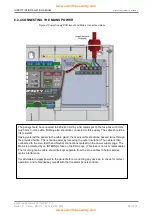
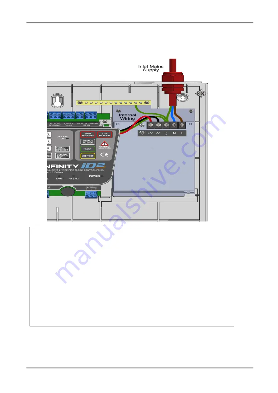
6.2.4 CONNECTING THE MAINS POWER
Figure 3: Power Supply PCB layout and Mains connection details
The panel should be connected to 220-240V AC by a 3A rated spur to the fuse box with 1mm
2
to 2.5mm
2
3-core cable. Nothing else should be connected to this supply. The cable should be
fire resistant.
Having entered the panel via the cable gland, the mains cable should be passed twice through
the provided ferrite. This is made easier by removing the outer insulation. The cable is then
connected to the Live, Earth and Neutral connections marked on the power supply cage. The
Mains is protected by an INTERNAL fuse on the PSU cage. (This fuse is not user replaceable)
The incoming mains cable should be kept separate from the zone cables to help minimise
mains interference.
It is advisable to apply power to the panel before connecting any devices, to check for correct
operation, and to familiarise yourself with the fire alarm panels controls.


