


RPC-2 REVERSE PULSE DUST COLLECTOR
Page 4
© 2012 CLEMCO INDUSTRIES CORP.
www.clemcoindustries.com
Manual No. 22788
2.3.5
Check the amperage on initial start up. If the
motor draws excessive amperage, gradually close the
damper until the amperage is within the specifications
shown on the motor plate. The damper is located on the
exhauster outlet.
2.4
Flex Hose Connection
2.4.1
Connect the flexible exhaust hose between the
reclaimer outlet adaptor and dust collector inlet adaptor.
It may be easier to slip the hose over the adaptors, and
create a tighter seal, if the first two or three inches of
wire is removed from the inside of the hose. Use care
not to damage the hose. Secure the hose with worm
clamps. NOTE: The hose wire helps dissipate static in
the conveying hose, and helps ground each segment. In
order for the hose wire to dissipate static electricity, the
wire must touch the metal of each segment.
2.5 Ground
Cabinet
2.5.1
To prevent static electricity build up, attach an
external grounded wire from an earth ground to the
grounding lug located on the rear wall of the collector.
2.6
Compressed Air Connections
NOTE: For maximum filter life and efficiency, the pulse
air source should be 30% relative humidity or less, and
be free of any oil contaminants. If line air does not meet
this requirement, an air dryer is recommended.
2.6.1
Connect a 1/2" or larger air hose to the pressure
regulator located on the pulse manifold inlet. An isolation
valve should be installed at the air source to enable
depressurization for service. If rigid pipe is used for the
air line, a flexible section of hose must be used at the
connection, to enable the top access door to swing open
for service.
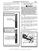
WARNING
If twist-on type air hose couplings are used,
they must be secured by safety pins or wires to
prevent accidental disconnection while under
pressure. Hose disconnection while under
pressure could cause serious injury.
2.7
Install Manometer, Refer to Section 4.4
3.0 OPERATION
WARNING
All persons operating this equipment must be
made aware of the hazards of abrasive blasting.
Prolonged exposure to any dust could result in
serious lung disease and death. Short term
ingestion of toxic materials, such as lead dust
or dust from other heavy metals and corrosives,
could cause serious respiratory injury or death.
Identify all materials that are to be removed by
blasting, and obtain a Materials Safety Data
Sheet (MSDS) for the blast media. If lead
coating or other toxic materials are being
removed by the blasting process, HEPA after-
filters must be used for those applications.
3.1 Initial
Start-up
3.1.1
The dust collector access doors and dust drawer
must be closed when the dust collector is on.
CAUTION
Do not pulse new dust collectors or
replacement cartridges until the cartridges are
properly seasoned. Refer to Section 6.2.
Pulsing unseasoned cartridges could cause
premature cartridge failure or decrease the
efficiency of dust collector.
3.1.2
With the sequence switch OFF, open the
compressed air supply valve to pressurize the pulse
manifold. Check the air line and connections for leaks.
3.1.3
Using the regulator on the manifold inlet, turn
pulse pressure to 20 psi. Turn the sequence switch ON,
and check the air pulse and sequence of the diaphragm
valves, solenoids, and panel timer. After the operation of
the pulse system is confirmed, turn the sequence switch
OFF and increase pressure to 70 psi.
3.1.4
Do not turn the sequence switch ON until the
cartridges are seasoned per Section 6.2.
3.2 Operation
Start-Up
3.2.1
Make sure the top access door is secured with
clamps, and that the dust drawer is closed.
3.2.2
Make sure the sequence switch is on. NOTE: Do
not turn the sequence switch ON until the cartridges are
properly seasoned, per Section 6.2.


