background image


RPC-2 REVERSE PULSE DUST COLLECTOR 

Page 7 


© 2012 CLEMCO INDUSTRIES CORP.  

  www.clemcoindustries.com  

  Manual No. 22788   

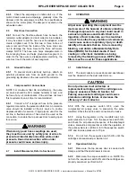
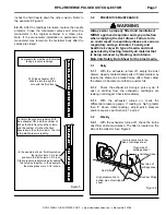
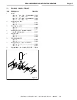
inches the fluid travels down the other column. Refer to 
the example in Figure 5. 
 

4.4.10

  After the readings are taken, replace the needle 

protector. Close the manometer valves and store the 
manometer in the original container in a clean area. 
Note: If the manometer installation is permanent, the 
manometer may remain on the reclaimer body after the 
valves are closed. 


Figure 5 


5.0 PREVENTIVE 

MAINTENANCE


WARNING 

Always wear a properly fitted and maintained, 
NIOSH approved respirator and eye protection 
when emptying the dust drawer. Failure to do 
so could result in respiratory disease or serious 
respiratory and eye irritation. Toxicity and 
health risk vary with type of media, and dust 
generated by blasting. Identify all material that 
is being removed by blasting, and obtain a 
Materials Safety Data Sheet for the blast media.


5.1 Daily


5.1.1

  With the exhauster turned off, empty the dust 

drawer. Heavily contaminated parts or friable media may 
require the drawer be emptied more often. Never allow 
the drawer to become more than a quarter full. 

 
5.1.2 

Check the exhaust air during a pulse cycle. If 

dust is emitting from the exhauster, cartridges are 
leaking or damaged. Check immediately. 
 

5.1.3

  With the exhauster turned on, check the 

differential pressure gauge. If reading is high (greater 
than 4" above initial reading), adjust pulse pressure 
and/or sequence per Section 4.1 and 4.2. 
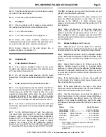
 

5.2 Weekly


5.2.1


With the exhauster turned off, check the in-line 

dust filter dust accumulation. The filter is located on the 
side of the collector. See Figure 6. 
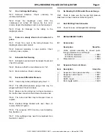


 Figure 


Cartridge Sheet

Clean side of 
cartridge sheet 

Dust side of 
cartridge sheet

Snubber Fitting

Low pressure line to top 
side of cartridge sheet 

High pressure line to 
bottom side of cartridge 
sheet 

Dust Filter

The manometer must be vertical when 

taking pressure readings. 

With the exhauster OFF, 

slide the rule to align the 

zero with the fluid level. 

In the example shown, fluid traveled up 

the right column 1-3/4 inch, 

and down the left column 1-3/4 inch. 

Static pressure is determined by adding 

the columns together. In the example, 

the static pressure is 3-1/2 inches. 


To obtain the pressure reading: With 
the exhauster ON, add the number of 
inches the fluid travels up the column, 
and the number of inches the fluid 
travels down the other column. The total 
is the static pressure reading. 

Содержание RPC-2

Страница 1: ...the combination of products determined by the user in his selection nor as to the compliance with regulations or standard practice of such combinations of components or products It is the responsibili...

Страница 2: ...ssages that follow this symbol to avoid possible injury or death CAUTION Caution used without the safety alert symbol indicates a potentially hazardous situation which if not avoided may result in pro...

Страница 3: ...timing sequence energizes when the exhauster is turned on automatically pulsing the cartridges when the exhauster is running If the switch is OFF the timer will not energize and the cartridges will no...

Страница 4: ...ts to the RPC Control Panel Pulse Sequence Panel must also be provided by the user If the RPC Collector replaces an existing push through collector or dust bag the exhauster may be wired into the cont...

Страница 5: ...s or wires to prevent accidental disconnection while under pressure Hose disconnection while under pressure could cause serious injury 2 7 Install Manometer Refer to Section 4 4 3 0 OPERATION WARNING...

Страница 6: ...me more air but will NOT increase cleaning efficiency 4 2 4 When the frequency of the pulse cycles will not lower the differential pressure to less than 4 or if a decrease in the efficiency is noted i...

Страница 7: ...ing instructions for the manometer 4 4 2 Connect one end of the 3 16 ID tubing to one of the tubing connectors elbow at the top of the manometer by pushing it over the barbed adaptor 4 4 4 Leaving the...

Страница 8: ...to become more than a quarter full 5 1 2 Check the exhaust air during a pulse cycle If dust is emitting from the exhauster cartridges are leaking or damaged Check immediately 5 1 3 With the exhauster...

Страница 9: ...ter each cartridge install venturi tube and secure with hold down plates 6 1 8 Inspect the access door gasket replace if worn or damaged Close the access door and secure 6 1 9 Reset timer OFF time to...

Страница 10: ...7 5 2 The differential pressure gauge lines may be plugged with dust Check and clean 7 5 3 Make sure the tubing has not been inserted so far into the tube connection that it blocks the tube ends 7 5...

Страница 11: ...Fitting 1 4 NPT bulkhead 05605 8 Petcock 1 4 NPT 01993 9 Gauge pressure 11826 10 Gauge differential pressure 10188 11 Snubber fitting 15786 12 Ground lug 11639 13 Tubing 1 4 nylon specify feet requir...

Страница 12: ...cfm 2 Hp 230 V 3 ph standard 12309 900 cfm 2 Hp 230 V 1 Ph 02979 2 Plate motor mount 600 cfm 12004 900 cfm 12005 3 Housing exhauster 600 cfm 12272 900 cfm 12271 4 Gasket 5 16 x 1 adhesive backed speci...

Отзывы: