
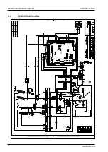

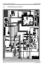


ZHD 2500-130/150
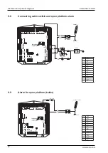
Connection unit
49
www.zepro.com
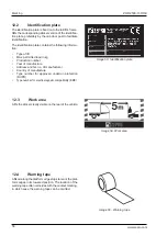
11.2.1
Information codes
Codes are shown on the display in a sequence. First a letter for identification of information, fol
-
lowed by figures or segments for further information and then ending with a pause:
When the CS (cabin switch) is switched on, the current program configuration (P) is displayed
first, followed by configuration number.
The number of volts detected is then displayed and, after
this, the current software version (J), followed by version number.
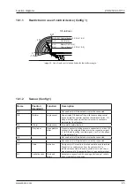
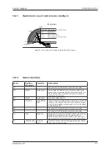
As long as no control device is used, a scrolling sequence is then displayed, with sensor indication
(C), followed by 0-6 segments showing which sensors have a signal.
When a control device is used, the control device being used (1-7) is displayed, followed by which
button has been pressed, segments B, C, E or X (X symbolises the 4th button on the respective
control device (2h1 for fixed control device 1, 2h2 for fixed control device 2, lock knob for radio
control device and coil control device).
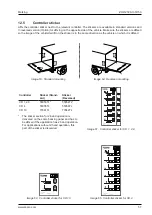
The control devices are symbolised by the figures 1-7
Control card con-
nection
Recommended control device
1
CTRL 1
Fixed control device 1, including two-hand button 2h1
2
CTRL 2
Fixed control device 2, including two-hand button 2h2
3
CTRL 3
Radio control device, External
4
CTRL 4
Coil control device
5
CTRL 5
Slider lift control device
6
CTRL 6
Radio control device, internal module
7
CS
CS (cabin switch)
Once a button has been released, the control system for the current control device is locked for
a while to ensure that no other person operates the lift from another control device. During the
period the control system is locked for the current control device, its number (1-7) will flash on the
display. This primarily applies to radio and coil control devices, as other control devices have such
a short locking period that there is hardly time to see the indication.
Ctrl 4 can be equipped with a locking function. Once the control device has been used, the control
system is locked until it is unlocked manually from the respective control device’s deactivation button.
The radio control device is also equipped with a locking function. The control system can then
be locked/unlocked via the remote control lock button. On certain models, the status of the lock
is indicated by LED which lights when the lock is activated. In the event of a fault in the remote
control, unlocking can be performed by turning the control power (CS) Off/On.
On certain remote control models, the lift locks again as soon as a button on the remote control is
pushed when the lift is unlocked by the control power (CS) being switched Off/On.
The lift remains locked if it loses power and is then started up again, and the number 6 flashes
on the control card’s display. Unlocking is performed as described above.
NOTE.
Содержание ZHD 2500-130
Страница 2: ......
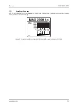
Страница 65: ...ZHD 2500 130 150 Specifications 65 www zepro com Image 71 Loading diagram 16 4 Loading diagram...
Страница 67: ...ZHD 2500 130 150 Specifications 67 www zepro com...