


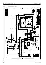

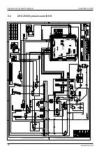


ZHD 2500-130/150
Installation
25
www.zepro.com
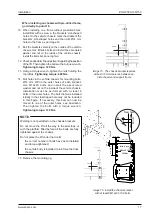
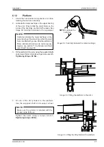
2x M12x100 8.8
80 Nm
2x M12x80 8.8
80 Nm
2x M12x80 8.8
80 Nm
2x M12x100 8.8
80 Nm
6.7
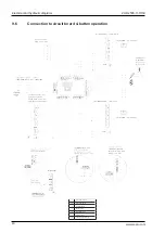
Underrun protection
6.7.1
Installation
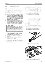
Test the position of the underrun protection without
tightening the bolts to check that the statutory dimen-
sions are obtained. Adjust if necessary then tighten
the bolts with a torque wrench.
1. Fit the inner part of each bracket at one of four
heights. Select the height that meets the statutory
requirements, see section "6.6.2 Statutory dimen-
sions for underrun protection" on page 23. Use the
corresponding bolts M12x100. Assemble without
tightening the bolts, see Image 31.
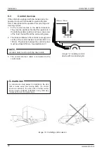
2.
Fit the outer part of each bracket at one of five
positions. Select a position that meets the statu-
tory requirements, see section "6.6.2 Statutory
dimensions for underrun protection" on page 23.
Check carefully that there is no risk of the outer
part of each bracket colliding with any part of
the cylinders when using the lift’s functions. In
particular, check in relation to the cylinders’ hose
connections, especially when the outer part of
the brackets is installed a long way in.
m
WARNING!
Use the corresponding bolts M12x80. Assemble
without tightening the bolts. See Image 32.
3. Check that the installation meets the statutory
requirements.
4. Tighten all the bolts using a torque wrench.
Tightening torque: 80 Nm.
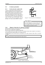
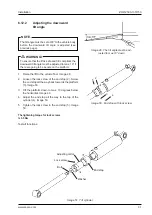
5. Fit the beam end caps, rotated so the logo is the
right way up, and press them firmly to secure. If
necessary, tap carefully with a rubber hammer.
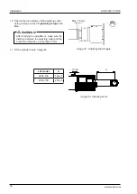
Image 31. The inner part of the brack-
ets can be fitted at one of four heights
Image 32. The outer part of the brack-
ets can be fitted in one of five positions
Image 33. Fit the beam end caps
Image 34. Installing underrun protection
133
193
241
301
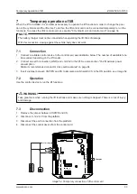
617
667
717
767
817
Содержание ZHD 2500-130
Страница 2: ......
Страница 65: ...ZHD 2500 130 150 Specifications 65 www zepro com Image 71 Loading diagram 16 4 Loading diagram...
Страница 67: ...ZHD 2500 130 150 Specifications 67 www zepro com...