background image

4

Supersedes 08-19-05 Z08-00481B

  05-18-06   Z08-00481B

        ELECTRICAL INSTALLATION

PRE START-UP

OPERATING

INSTRUCTIONS

  WARNING:  ELECTRICAL SHOCK HAZARD

 AVERTISSEMENT:  LE DANGER ELECTRIQUE DE CHOC

 ADVERTENCIA:


CHOQUE  ELÉCTRICO PELIGRO

1.

The first time the machine is operated, after

repairs have been made, or if the machine has set
for a period of time (30 days or more) follow the
following procedures.
A. Check the tension of the belt (if so     equipped)

per instructions in 

MACHINE


MAINTENANCE

.

B. Flush the machine per instructions in

MACHINE


MAINTENANCE

.

C. Install float tank drain plug (if so equipped).

D. Open float tank ball valve (if so equipped).

CAUTION:  

Always use the factory supplied wash

hose with your machine. 

Do  not

 substitute other

hoses as a potential safety problem may develop.

CAUTION:

 If machine has been exposed

t o sub-freezing  temperatures, it must be
thoroughly warmed to above freezing before
operating.  Failure to warm machine can cause
damage to the pump packings and other
components.

2.   Read and observe all items in “CLEANER
      INSTALLATION”.

♦   

Refer to the 

MAINTENANCE


SCHEDULE

 for any

     maintenance to be performed before operation.

ELECTRICAL

:     Connect the machine to an

electrically grounded circuit that is fuse or   circuit
breaker protected.  Do not use any type of adapter.
If the correct type of receptacle is not available,
have one installed by a qualified  electrician.

OIL


LEVEL

:  Check the oil level in the water pump.

BELT

:  Make sure belt tension and condition is as

specified in MACHINE MAINTENANCE.


METERING VALVE ( 

if so equipped):  Make sure

the metering valve is closed before operation. If air
enters the system through this valve, poor
performance and machine damage will occur.  Refer
to the metering valve insert for proper operation.

WATER


SUPPLY

:  This machine must have a water

supply meeting or exceeding the maximum
discharge volume specified in the PERFORMANCE
section, and a minimum water inlet pressure of 40
PSI /12.1KGM.

LIME:

 Water containing large amounts of lime,

calcium or other similar materials can produce a
coating on the inside of the spray tip, impact nozzle
and coil pipe.


1. 

 ELECTRICAL

:  Connect the machine to an

        electrically grounded circuit that is fused or    circuit
       breaker protected. The circuit must match that
       specified in  the  ELECTRICAL   section under

       MODEL


SPECIFICATIONS.

WARNING:

  To reduce risk of electrocution, keep all

connections dry and off the ground.  Do not
touch plug with wet hands.

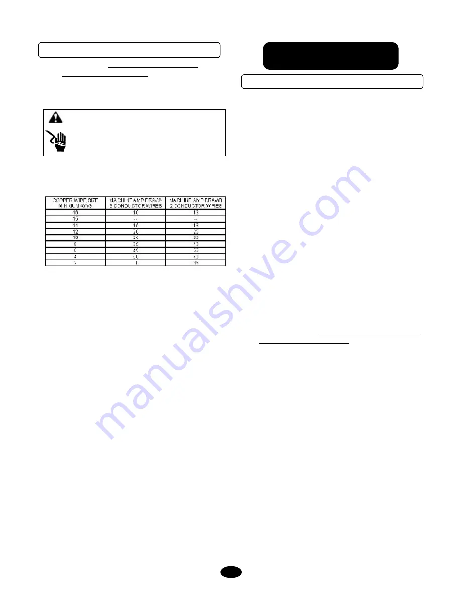
CHART FIGURES ARE BASED ON NOT MORE THAN
100 FOOT

(Based on Ambient Temperature of 86°F (30°C)).

*Use Amp Draw indicated the same or higher than your
machine output.

EXAMPLE

:  Machine Amp Draw 51, use 55 (2 Conductor).

The thermostat type of cord shall be C, PD, E, EO, EN, S,
SO, SRD, SJ, SJO, SV, SVO, SP.
The thermo set plastic types shall be ET, ETT, ETLB, ETP,
ST, STO, SRDT, SJT, SJTO, SVT, SVTO, and SPT.

  2.

  EXTENSION CORD:

  The use of an extension cord

that has undersize wire compared to the amp draw of
your machine will adversely limit the starting load
carrying abilities of the motor and machines
performance.  Use only 3-wire extension cords that
have 3-prong plugs and  3-pole cord connectors that
accept the plug from the product.  Use only
extension cords that are intended for outdoor use.
These extension cords are identified by a marking
“Acceptable for use with outdoor appliances; store
indoors while not in use.”  Use only extension cords
having an electrical rating not less than the rating of
the product.  Do not use damaged extension cords.
Use an extension cord in good repair free of frays or
cracks in the outer covering.  Do  not abuse
extension cord and do not yank on any cord to
disconnect.  Keep cord away from heat and sharp
edges.  Always disconnect the extension cord from
the receptacle before  disconnecting the product from
the extension cord.

Содержание 212 CD

Страница 1: ...Servic e Manua l Servic e Manua l g distribu com 212 CD p n N84201...

Страница 2: ...______________________ MAKE MODEL SERIAL NUMBER ______________________________________________________ SELLER ______________________________________________________ ADDRESS CITY STATE ZIP ____________...

Страница 3: ...650400 2B 4 0 15 p n JA0 15040 2 Dimensions L 29 H 23 W 22 Trigger Gun Wand Trigger p n C210a 00701 Trigger Gun p n J06 00121 Trigger Wand p n J06 00174 Hose Assembly E212 00710 Assembly Hose 3 8 x 25...

Страница 4: ......

Страница 5: ...tment See Parts List Section Unloader Pressure Adjustment See Parts List Section WARRANTY Inside Back Cover SPECIFICATIONS Inside Front Cover SCHEMATIC Last Page SAFETY INSTRUCTIONS Safety Symbols 3 G...

Страница 6: ...NUMBER ON ALL ORDER BILLS THIS PROCEDURE WILL ENABLE NEEDED PARTS TO BE SHIPPED QUICKLY READ ALL Installation Operation and Maintenance instructions before operating the machine NOTE Refer to CLEANER...

Страница 7: ...company or seller for details 10 If a water leak is found DO NOT OPERATE THE MACHINE Shut off the motor and repair 11 Follow instructions on how to stop the machine and bleed pressures quickly Be tho...

Страница 8: ...a water supply meeting or exceeding the maximum discharge volume specified in the PERFORMANCE section and a minimum water inlet pressure of 40 PSI 12 1KGM LIME Water containing large amounts of lime c...

Страница 9: ...EMICAL CHEMICAL Use factory recommended chemicals for best cleaning action and for extended pump life Contact your dealer for chemicals available Follow instructions on chemical container Note If the...

Страница 10: ...cal line Air heats very quickly and needs to be eliminated before the burner can be turned on Open the metering valve counter clockwise with the trigger gun open allowing the chemical to come up the c...

Страница 11: ...the antifreeze will dilute with use 6 Install a 2 ft garden hose to the water inlet Insert the other end into a container of antifreeze solution 7 With the gun assembly in hand turn on the switch On t...

Страница 12: ...rrect tension see MACHINE MAINTENANCE insert LEAKS Check for water and buildup of scale at pipe connections SCREEN WATER Check Inlet Hose Screen for debris Check float Tank Hose Screen if so equipped...

Страница 13: ...isposal instructions F See Low operating pressure A Replenish supply B Turn metering valve knob to open C Remove screen and cleaan D Tighten all fittings and hoses for the chemical line E Disassemble...

Страница 14: ...connect switch Replace fuse if blown B Call service technician C Call service technichian or take motor to repair Warranty station A Machine must be thoroughly warmed to above freezing B Call service...

Страница 15: ...IPTION QTY 1 4120 00902P ASSEMBLY CHEMICAL LINE 1 2 C210A 00701 ASSEMBLY GUN 1 3 E212 00603 ASSEMBLY CLEANER 1 4 E212 00710 ASS Y HOSE 3 8 X 25 5000 PSI 1 5 F04 00451 GROMMET RUBBER 5 6 J00 15040 2 TI...

Страница 16: ...SEMBLY GUN ITEM NO PART NUMBER PART DESCRIPTION QTY 1 J06 00121 GUN TRIGGER RL24 1 2 J06 00174 WAND GUN 24 1 3 W04 24221 2 COUPLER SOCKET 1 E212 00710 PART LIST ITEM PART NUMBER PART DESCRIPTION 1 W04...

Страница 17: ...Trigger Gun Wand...

Страница 18: ...TOR ELEC 2 3HP 1 6 F04 00179 CORDSET GFI 115V X 15 1 7 F04 00310 CONNECTOR CONDUIT 1 8 F04 00716 SWITCH TOGGLE 115V 15AMP 1 9 F04 00716 1 PLATE TOGGLE SWITCH 1 10 G02 00018A ASS Y TIRE RIM 10 2 11 H04...

Страница 19: ...RIPTION QTY 1 C04 00121 SCREEN GARDEN HOSE 1 2 C05 00270 1 NUT GARDEN HOSE 1 3 C05 00272 ADAPTER GARDEN HOSE 1 4 N07 00121 PUMP WATER 1 5 W04 34231 A COUPLER QUICK DISCONNECT 1 ASSEMBLY PUMP p n E212...

Страница 20: ...REAR C RANKCASE COV ER TO CRANKCASE 7 FT LBS 1 0 KG M HEAD TO CRANKCASE 15 FT LBS 2 0 KG M NOTE When plunger screw is removed it is important you install a new copper washer and flinger washer to ensu...

Страница 21: ...Water Pump EXPLODED VIEW 12 06 05 Z08 05302 PARTS LIST 06 14 05 Z08 01242 6 3...

Страница 22: ...lation in step 7 6 Malfunctioning valve assemblies must be replaced 7 Lubricate a new o ring with the pump crankcase oil and install into valve cavity in the head Install a good valve assembly into th...

Страница 23: ...ers 1 When the plunger screw is removed it is important to install a new o ring anti extrusion and copper washers 2 Remove the plunger retaining screw by turning counterclockwise Remove and replace co...

Страница 24: ...y 5 Examine male and female adapters discard worn items Trial fit the female adapters into the head checking for binding or damage Discard and replace damaged items 6 Lubricate packing cavities in the...

Страница 25: ...the outer plungers are projecting the same distance from the crankcase 3 Lubricate the exposed plungers with crankcase oil 4 Start the head onto the plungers and using a soft mallet tap the head evenl...

Страница 26: ...13 Pump Maintenance Record Pump Maintenance Record Oil Change Month Day Year Operating Hours Oil Brand Type Pump Service Month Day Year Operating Hours Type of Service...

Страница 27: ...14 Pump Maintenance Record Electrical Schematic...

Страница 28: ...indow gasket or rear cover Replace gasket or o ring Oil gauge loosed Tighten oil gauge Rear cover screws loose Tighten rear screws to torque values in PUMP SPECIFICATIONS Pump overfilled with oil disp...

Страница 29: ...S Water leakage from under head Worn packing Install new packing Cracked scored plunger Remove and replace plunger Failure of plunger retainer o ring Remove and replace plunger retainer o ring Loud kn...

Страница 30: ...check valves Clean replace check valves Foreign particles in valve assemblies High inlet water temperature See temperature in PUMP SPECIFICATIONS Excessive vibration Dirty or worn check valves See Di...

Страница 31: ......

Страница 32: ...For full warranty information contact your delivering distribu tor or contact the manufacturer at info warrantysvc com...

Отзывы: