MAXinBOX FC 0-10V FAN
http://www.zennio.com
Technical Support:
http://support.zennio.com
34
34
ANNEX I: INDEPENDENCE OF THE MODULES
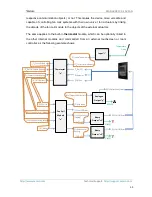
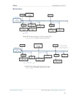
The following figures illustrate how the communication objects and group addresses of
the fan coil and the outputs modules should be linked depending on the system to
control.
Two-Pipe Fan Coil System
Four-Pipe Fan Coil System
It is worth emphasising that
the two fan coil modules are completely independent
of the analogue and binary outputs modules
. It is up to the integrator whether to
control the fan coil module together with the built-in outputs modules (by grouping their
[FCx] On/Off
[FCx] Control Variable (Cooling)
[FCx] Control Variable (Heating)
[FCx] Mode
Fan Coil
Module
“x”
Analogue
Output “y”
0
-10 VDC
Binary
Output “z”
[
AO
Y
] Output Value (Status
)
[
O
Z
] On/Off (Status)
On/Off
[
AO
Y
] Output Value (Control
)
[FCx] Fan Speed
[FCx] On/Off (Status)
[FCx] Valve Control
[
O
Z
] On/Off
[FCx] On/Off
[FCx] Control Variable (Cooling)
[FCx] Control Variable (Heating)
[FCx] Mode
Fan Coil
Module
“x”
Analogue
Output “y”
0
-10 VDC
Binary
Output “z
1
”
[
AO
Y
] Output Value (Status
)
[
O
Z1
] On/Off (Status)
On/Off
[
AO
Y
] Output Value (Control
)
[FCx] Fan Speed
[FCx] On/Off (Status)
[FCx] Valve Control
(Heating)
[
O
Z1
] On/Off
Binary
Output “z
2
”
[
O
Z2
] On/Off (Status)
On/Off
[FCx] Valve Control
(Cooling)
[
O
Z2
] On/Off
)


