Safety Measures
OPMI LUMERA® 700
Version 7.3
Page 44
G-30-1673-en
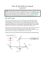
Device connector signs
1
Potential equalization
For connection of the system to the potential equalization system.
2
"Connector for foot control panel" label
3
Remote connector
This label identifies a connection on the device with max. 24V/0.5A
4
"CAUTION" label
Warning of a potential hazard
5
Defined user group
Identifies the service interface.
6
Power outlet socket
Only connect devices with the correct electrical ratings.
7
Video component connector
This label identifies the connections for additional video components
8
Video signal output port
(e.g., for video components, such as monitors or recording devices)
9
Video signal output/input port
(with SD video camera only)
10
USB port
Identifies the connector e.g. for USB sticks
100V - 240V AC
max. 500VA
USB
Содержание opmi lumera 700
Страница 1: ...Carl Zeiss OPMI LUMERA 700 User manual G 30 1673 en Version 7 3 2012 05 02...
Страница 4: ...OPMILUMERA 700 Version 7 3 Page 4 G 30 1673 en...
Страница 25: ...Version 7 3 G 30 1673 en Page 25 OPMI LUMERA 700 Safety Measures Fig 1 Safety Equipment 1 4 2 6 7 5 3 8...
Страница 31: ...Version 7 3 G 30 1673 en Page 31 OPMI LUMERA 700 Safety Measures Fig 4 Labels on the microscope 7 5 6 8 1 2 3 4...
Страница 46: ...Safety Measures OPMI LUMERA 700 Version 7 3 Page 46 G 30 1673 en...
Страница 49: ...Version 7 3 G 30 1673 en Page 49 OPMI LUMERA 700 System Overview Fig 17 System overview 6 7 2 1 3 5 4...
Страница 57: ...Version 7 3 G 30 1673 en Page 57 OPMI LUMERA 700 System Overview Fig 21 Components of the surgical microscope 5...
Страница 61: ...Version 7 3 G 30 1673 en Page 61 OPMI LUMERA 700 System Overview Fig 23 Overhead display 11...
Страница 71: ...Version 7 3 G 30 1673 en Page 71 OPMI LUMERA 700 System Overview Fig 29 Controls of XY coupling 1...
Страница 89: ...Version 7 3 G 30 1673 en Page 89 OPMI LUMERA 700 System Overview Fig 39 Display and control panel 1 2 3 1 2...
Страница 103: ...Version 7 3 G 30 1673 en Page 103 OPMI LUMERA 700 System Overview Fig 46 Ports on the 22 TFT 1 2 3 4 5 6...
Страница 106: ...System Overview OPMI LUMERA 700 Version 7 3 Page 106 G 30 1673 en...
Страница 109: ...Version 7 3 G 30 1673 en Page 109 OPMI LUMERA 700 Preparations for use...
Страница 111: ...Version 7 3 G 30 1673 en Page 111 OPMI LUMERA 700 Preparations for use Fig 47 Transport position of the 22 TFT 2 3 1 4...
Страница 113: ...Version 7 3 G 30 1673 en Page 113 OPMI LUMERA 700 Preparations for use Fig 48 OR scene 1 2...
Страница 115: ...Version 7 3 G 30 1673 en Page 115 OPMI LUMERA 700 Preparations for use Fig 49 Connecting the system 2 5 1 3 4...
Страница 137: ...Version 7 3 G 30 1673 en Page 137 OPMI LUMERA 700 Preparations for use Fig 64 Connecting the foot control panel 3 1 2...