background image


18 

9. Acquiring a Z-series 

Having set the system to acquire a satisfactory image, you can acquire a z-series. It may 
be worthwhile changing the frame size to 512×512 to minimize file size and to speed 
acquisition.  
 
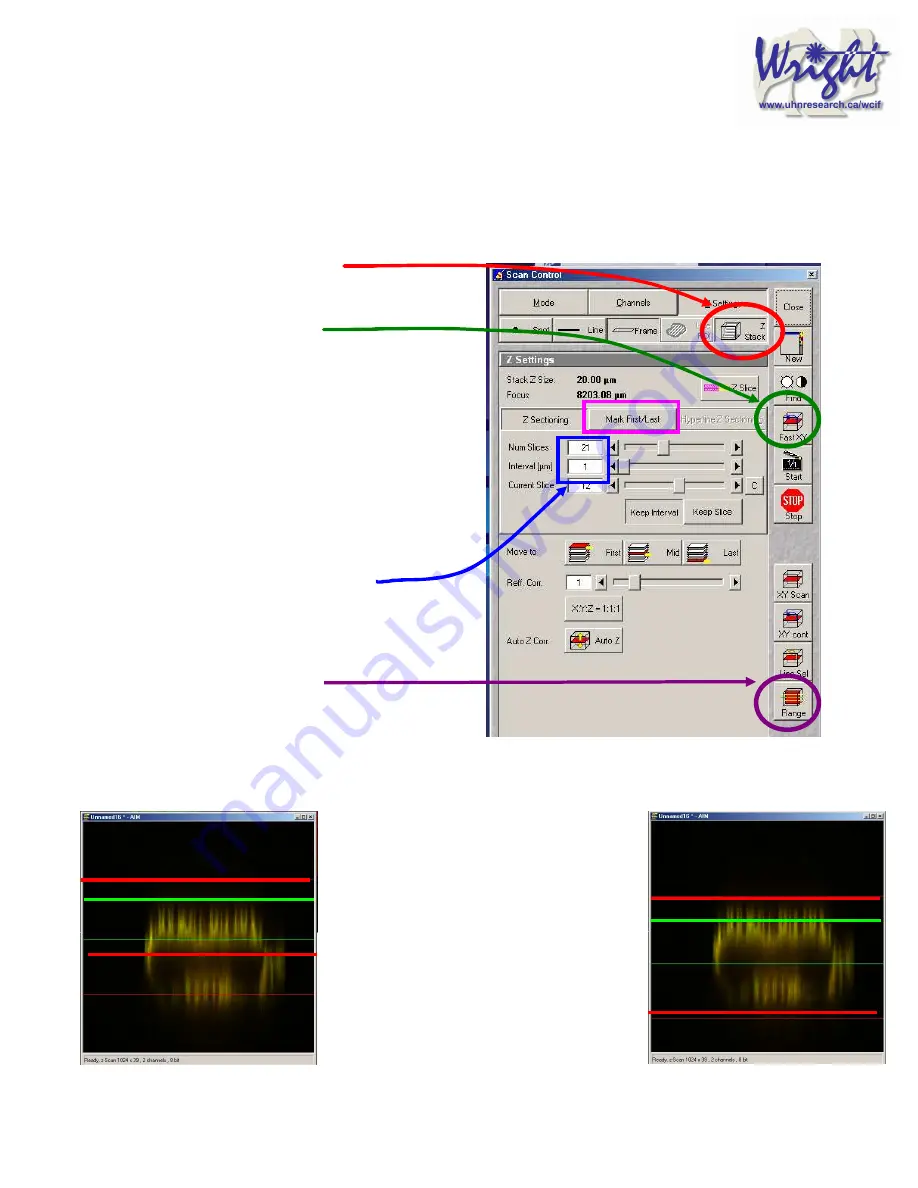
Click on the 

Z-Stack 

 button in the 

Scan control

 window. 

 
Using 

Fast scan  

mode to acquire a continuous image of the 
specimen. Focus up and down with the 
microscope focus wheel to ensure your 
specimen is in the centre of the field of view 
and the microscope is focused in the middle of 
the specimen. 
 
Stop acquisition. 
 
You can now precisely define the middle and 
depth of you z-series.  
 
Ensure the 

Num Slices

 = 20 and the 

Interval

 = 1 µm at this point to ensure the top 

and bottom of the specimen is located. 
 
Click the 

Range 

 button from the 

Scan control

 window – this 

will generate a side view of you specimen. 
This button is not available if the 

MarkFirst/Last


button is depressed. 


(LEFT) The green line represents the 
middle of your z-series. The upper red 
line represents the top and the lower red 
line the bottom of the z-series. 
(RIGHT) Drag the green line to the 
centre of the specimen and the red lines 
to just outside the top and bottom of the 
specimen. 

Содержание LSM 510

Страница 1: ...Quick Start Zeiss LSM 510...

Страница 2: ...IRING YOUR FINAL IMAGE 15 8 SAVING YOUR FINAL IMAGE 17 9 ACQUIRING A Z SERIES 18 10 ADVANCED OPTIONS 20 10 1 SINGLE TRACK SIMULTANEOUS ACQUISITION 20 10 1 1 Getting the display ready 20 10 1 2 Optimis...

Страница 3: ...cury lamp is turned on it should be left on for at least 30 minutes Once the lamp has been turned off it should not be turned on again for 30 minutes Remote control PC power IF REQUIRED UV laser power...

Страница 4: ...Double click the LSM 510 desktop icon The Zeiss LSM 510 switchboard window will appear Make sure Scan New Images is pressed and then click the Start expert mode button If Scan New Images is not presse...

Страница 5: ...the desired lasers position HeNe s to ON Argon to Standby When the Status reads Ready click the On buttons Also turn OFF any lasers that have been left on for you but you will not be using If the pre...

Страница 6: ...the body of the microscope The intensity of brightfield light is most easily adjusted with the Intensity control knob on the body of the microscope Arc lamp light can be shuttered on and off by either...

Страница 7: ...arc lamp light can be shuttered on and off by the FL button on the body of the microscope on the right hand side Brightfield halogen light can be switched on and off HAL button on the body of the micr...

Страница 8: ...MultiTrack button in the Configuration Control window Load the configuration that matches your fluorophores referred to as tracks by clicking the Config button Click on the drop down box and select a...

Страница 9: ...utton in the Acquire sub toolbar to open then Scan control window Click the Find button and the computer will open a new image window and calculate the approximate levels to generate a starting image...

Страница 10: ...ting the display ready This current type of display does not allow fine tuning of the imaging parameters and so needs to be adjusted Optimizing the confocal settings is best done with the image pseudo...

Страница 11: ...11 Your image window will now look like this...

Страница 12: ...ing detected Start with each at the optimum 1 Airy Unit by clicking the 1 button This will give different Optical Slice values for each channel Increase the pinholes of the shorter wavelength channels...

Страница 13: ...ng the max signal The max signal is set by adjusting the detector gain and laser transmission simultaneously You need to empirically work out the best laser power settings low laser power causes less...

Страница 14: ...t both channels stop scanning by pressing the Stop button in the Scan Control window Your image will look like this above Turn off the optimised channel in the Configuration Control window Turn on the...

Страница 15: ...nd click the Mode button Change the Frame size by clicking on the Optimal button see Appendix 1 for an explanation of this Noise can be reduced by averaging a number of frames and slowing the scan spe...

Страница 16: ...n the Single button in the scan control window to collect your final image bottom Click on the image window Info button This will bring up a bar on the left of the image window with the image informat...

Страница 17: ...ingle or multiple images or stacks Press Save as in the image window and the Save Image and Parameter window will open You can now chose to add your image to an existing database Open MDB button or cr...

Страница 18: ...d in the middle of the specimen Stop acquisition You can now precisely define the middle and depth of you z series Ensure the Num Slices 20 and the Interval 1 m at this point to ensure the top and bot...

Страница 19: ...and adjust the Pinhole so that each channel has the same optical section around 1 Airy unit but one channel will have to be slightly larger Readjust the red lines that indicate the top and bottom of...

Страница 20: ...is a delay between channels Sometimes this is unacceptable in particular for live cell imaging where the cell can move between channels creating artefacts In this case Single track mode should be use...

Страница 21: ...y steps up the gain and laser as it approaches the bottom reference slice 1 In the Scan Control Z settings window activate the Auto Z Corr 2 While in Fast XY scan mode focus to near the top of the sam...

Страница 22: ...this the microscope transmitted path needs to be set correctly Open the Microscope Control panel Toolbar Acquire then Micro The Field Stop iris needs to be fully opened 100 The Filter at 100 The trans...

Страница 23: ...ck return to imaging Try 10 as a first attempt In Excitation of Bleach Track set bleaching laser to 100 3 Click Define Region button to select bleach area 4 Define area to bleach then select it by tic...

Страница 24: ...rocess Bleached area 7 Save experiment 8 Create ROI reference image Turn ROI white by clicking the ROI colour button and selecting white Export this image for reference via the menu command File Expor...

Страница 25: ...turned on This will mean the top will need resetting and could result in damage to the 12 000 63 objective Turn off the epifluorescence lamp Cover the microscope avoiding the hot lamp housing 11 3 Exi...

Страница 26: ...e download and installation of an extra DAO file if you have Microsoft Office 2000 12 2 ImageJ http rsb info nih gov ij Plus Zeiss plugin http rsb info nih gov ij plugins lsm reader html Requires LSM...

Отзывы: