EN - 53
5.7.1
Connecting mains power to the CM
1.
Attach the connector of one 230 V AC power supply cable (Fig. 5.8, pos. 13) or one 24 V DC SELV
power supply cable (Fig. 5.8, pos. 11).
5.7.2
Connecting cables between CM and VMs
1.
Remove the white plastic protective cap from each VM. This will make the VM-PCB accessible.
2.
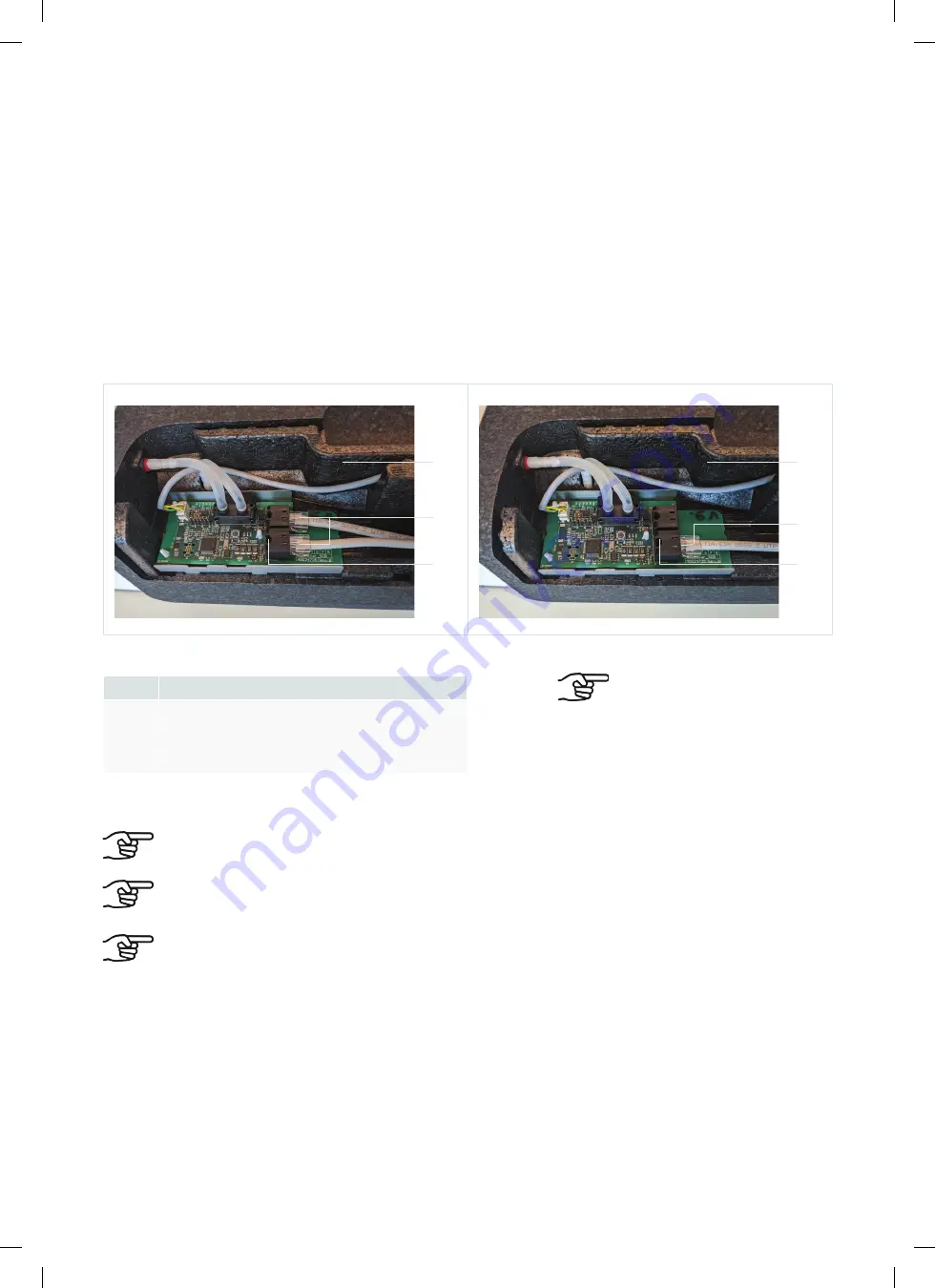
Connect one end of the ComfoNet RJ45 cable to the RJ45 socket (Fig. 5.8, pos. 10) of the CM.
Connect the other end of this ComfoNet-RJ45 cable to a ComfoNet-RJ45 socket (Fig. 5.10, pos. 3) of
the first VM (Fig. 5.9, pos. 1).
3.
Attach a second ComfoNet RJ45 cable to a free ComfoNet RJ45 socket (Fig. 5.10, pos. 3) on the first
VM and on a free ComfoNet RJ45 socket (Fig. 5.10, pos. 3) on the second VM (Fig. 5.10, pos. 1).
4.
Replace the protective covers of the VMs.
1
2
3
1
2
3
Fig. 5.9 – RJ45 sockets VM-PCB
Fig. 5.10 – RJ45 sockets VM-PCB
Pos.
Connection
1
VM
2
ComfoNet-RJ45 cable
3
ComfoNet-RJ45 socket (2x)
5.7.3
Connecting optional control components to the CM
The CM can control two VMs.
When the VM is switched on, the built-in motor is audible, as the built-in valve is first calibrated. This takes
about a minute.
Refer to the manual of the controlling component for the relevant settings.
1.
Connect the wiring of the existing controlling components to the CM.
There are two ComfoNet RJ45
sockets on each VM. These two
ComfoNet RJ45 connections
function identically, so connection
errors are excluded.
10001124369-0123-zw-zw-A4 ComfoVar Aero Installer_Service Zehnder-General_BOOK_2.indb 53
10001124369-0123-zw-zw-A4 ComfoVar Aero Installer_Service Zehnder-General_BOOK_2.indb 53
24-01-2023 11:11
24-01-2023 11:11


