EN - 3
4.2. Installation of the ComfoCool
Transport and unpacking
Take care when transporting and unpacking the unit. Only
transport it in an upright position. Keep it upright when
unpacking it. Make sure the packing material is disposed of
in an environmentally friendly manner.
Checking delivery
Contact your supplier immediately in case of damage or an
incomplete delivery. Besides the ComfoCool, the delivery
should include:
• Adaptor set (packed separately and specific to the unit
to which you will be mounting the ComfoCool);
• Power cable;
• Data cable for data exchange with the heat-recovery
unit;
• Manual;
• ComfoControl Luxe (either supplied or ordered sepa-
rately, depending on version).
The adaptor set is supplied in the following versions:
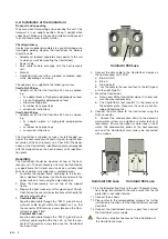
ComfoAir 350 luxe
• Adaptor set 930 for the ComfoAir 350 Luxe, compris-
ing:
• 2x adaptor block of high-grade polypropylene foam
• Front of high-grade polypropylene foam
• Steel mounting plate
• 4x rubber niche pipe rings
• conversion instructions
ComfoAir 550 luxe
• Adaptor set 950 for the ComfoAir 550 Luxe, compris-
ing:
• 2x adaptor plates of high-grade polypropylene
foam
• 4x rubber niche pipe rings
• conversion instructions
The ComfoCool is supplied as type L for left-handed ver-
sion of the heat-recovery unit and as type R for right-hand-
ed version of the heat-recovery unit. Check that the desig-
nation on the ComfoCool’s identification plate corresponds
with the designation on the heat-recovery unit’s identifica-
tion plate.
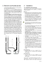
Assembly
The ComfoCool should be mounted on top of the heat-
recovery unit. The heat-recovery unit must be mounted on
a support frame that is level and stands on a suitably solid
floor. Each distinct assembly step is outlined below:
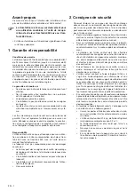
1. Assemble the support frame according to the instruc-
tions supplied. Then place it on the floor and ensure the
upper surface is level using the adjustable feet.
2. Place the heat-recovery unit on top of the support
frame.
3. Prepare the heat-recovery unit for mounting of Comfo-
Cool. Follow the conversion instructions attached to the
adaptor-set packaging.
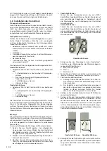
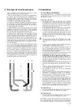
4.
ComfoAir 350 Luxe
Feed the data cable through the “DATA” gland. Ensure
sufficient cable length within the adaptor set, so that
the connector PCB remains accessible once the Com-
foCool has been fitted.
ComfoAir 550 Luxe
Feed the data cable through the “DATA” gland. Ensure
sufficient cable length within the unit, so that the con-
nector PCB remains accessible once the ComfoCool
has been fitted.
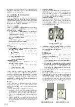
T
ComfoAir 350 Luxe
5. Connect the data cable to the ‘ComfoCool’ clamps on
the heat-recovery unit’s PCB.
a. Brown: GND
b. Blue: A
c. Blue/white: B
6. Lay the cable to the rear and then to the left (type L)
or to the right (type R).
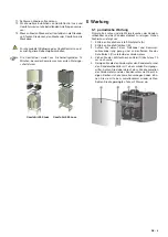
7. Mount the ComfoCool.
a. Note: never lift the ComfoCool alone. It is heavy and
must be mounted precisely;
b. The ComfoCool’s feet should fit in the recesses of
the adaptor plate. Make sure the seals do not dis-
lodge while doing this.
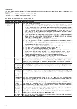
8. Connect the data cable to the ComfoCool using the
RJ45 connector.
9. Connect the condensation drain to the domestic
waste-water system via a siphon or a water lock of at
least 60mm. Ensure the siphon or water lock is full of
water. The condensation drains of the heat-recovery
unit and the ComfoCool must always be connected
with a siphon.
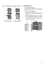
ComfoAir 350 Luxe
ComfoAir 550 Luxe
10. Fix the fall protection firmly to the wall. To prevent vibra-
tions being transmitted to the wall, ensure that the fall
protection is not under tension.
11. Connect the air ducts.
12. Please refer to the corresponding manuals for further
installation instructions for the ComfoControl Luxe and
ComfoAir.
13. Connect the ComfoCool’s mains supply then connect
the ComfoAir’s mains supply.
The order is important because of the initialization of
the ComfoControl Luxe.

