17 - EN
hot water (max. 40 °C).
b. Rinse the heat exchanger with clean hot tap wa-
ter (max. 40 °C).
c. Clasp the heat exchanger between both hands
(on the coloured side surfaces) and shake the
water from the heat exchanger.
Only an enthalpy exchanger with a blue co-
ver can be washed with water. When having
an enthalpy exchanger with a white cover
never wash it with water.
Do not use aggressive cleaning agents or
solvents.
If the fans or preheater element filter also
need maintenance do not re-install the heat
exchanger yet.
10.
If no more maintenance is necessary install
all parts in reverse order, reconnect the pow-
er and carry out the self-test in accordance
with menu P76
.
Fasten the screws to a maximum of 1.5 Nm.
This is roughly equal to setting 2 of an ave-
rage battery-powered drill.
2.9.2 Inspecting and cleaning the fans
Check the fans once every 2 years.
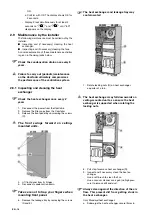
1. Remove the heat exchanger as instructed in the
maintenance chapter of the heat exchanger
2.
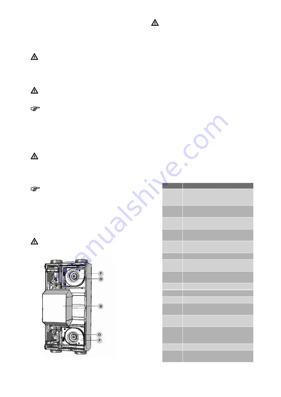
Remove
the inflow nozzle (F) by unscrewing the
2 screws surrounding the scroll casing.
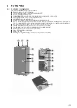
3. Inspecting and if necessary clean the fans (O).
- Use a soft brush to clean the fan impellers.
- Use a vacuum cleaner to remove dust.
Do not damage the fan impellers or tempe-
rature sensor.
4.
Install
all parts in reverse order.
5.
Carry out
the self-test in accordance with menu
P76.
Fasten the screws to a maximum of 1.5 Nm.
This is roughly equal to setting 2 of an ave-
rage battery-powered drill.
2.10 Malfunctions
Malfunctions in the ComfoAir are reported as follows:
■
The malfunction alert appears on the ComfoS-
ense panel;
■
The malfunction alert appears on the display;
■
The malfunction indicator on the 3-position
switch lights up.
Malfunction alerts may not appear on the digital oper-
ating device in all cases, even though there is a mal-
function (or problem). A concise explanation of both
types of malfunction (or problem) is given in the fol-
lowing paragraphs.
2.10.1 Malfunction alerts on the digital
operating device
In the event of a malfunction, the corresponding mal-
function code will be displayed on the digital operat-
ing device of the ComfoAir.
Below is a list of the malfunction alerts on the digital
operating device.
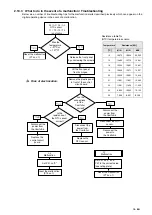
In the chapter about troubleshooting is explained
how to solve these malfunctions
Code
Description
A0
NTC sensor TGe is defective.
(= geothermal heat exchanger tem-
perature)
A1
NTC sensor T1 is defective.
(= outside air temperature)
A2
NTC sensor T2 is defective.
(= supply air temperature)
A3
NTC sensor T3 is defective.
( =return air temperature)
A4
NTC sensor T4 is defective.
(= exhaust air temperature)
A5
Malfunction in the bypass motor.
A6
Malfunction in the
Pre heater motor.
A7
Pre heater does not heat suffi-
ciently.
A8
Pre heater becomes too hot
E1
Exhaust fan not rotating.
E2
Supply fan not rotating.
EA1
Enthalpy sensor measures exces-
sive Relative Humidity (RH) values.
EA2
No communication between the
enthalpy sensor and the ComfoAir.
COMM
ERROR
No communication between the
ComfoSense panel and the Com-
foAir.
FLTR
Internal Filter is dirty.
FLTR
EXT
External Filter is dirty.
Содержание ComfoAir 200
Страница 1: ...Cooling Fresh Air Clean Air Heating ComfoAir 200 Installer manual...
Страница 4: ...EN IV...
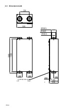
Страница 10: ...EN 6 2 3 Dimension sketch LEFT RIGHT CONDENSATION DRAIN...

