background image

9

10

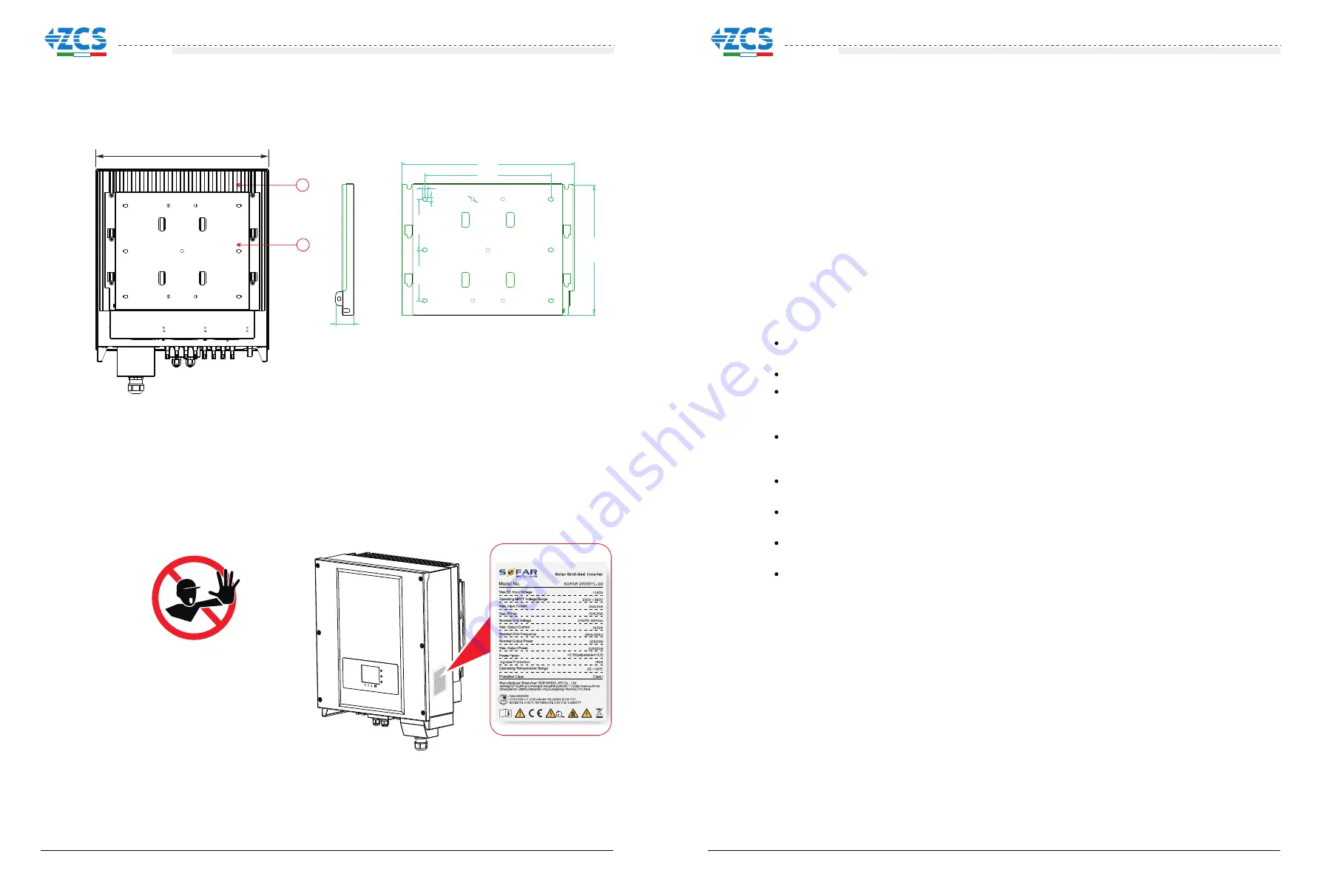
Identification labels of the equipment

The labels must NOT be hidden with 
objects  and  extraneous  parts  (rags, 
boxes,  equipment,  etc.);  they  must 
be cleaned regularly and kept visible 
at all times.

1. 

Heat sink    

2. 

Bracket

Figure2-9 Back view and Bracket dimensions

512.0mm

1

48mm

459mm

336mm

348.3mm

14mm

10mm

10mm

135mm

135mm

2

2.2 Function description

DC  power  generated  by  PV  array  is  filtered  through 

input  board 

before  entering  into  Power  board.  Input  board  also  offer  functions  such  as  insulation 
impedance detection and input DC voltage / current detection. DC power is converted to AC 
power by Power board. AC power is filtered through Output board then AC power is fed into 
the  grid.  Output  board  also  offer  functions  such  as  grid  voltage  /  output  current  detection, 
GFCI  and  output  isolation  relay.  Control  board  provides  the  auxiliary  power,  controls  the 
operation  state  of  inverter  and  shows  the  operation  status  by  Display  board.  Display  board 
displays  fault  code  when  inverter  is  in  abnormal  operation  conditions.  At  the  same  time, 
Control board can trigger the relay so as to protect the internal components.

string  detection  board  and 

Operating Principle

Operating Principle

The string detection board detects the input voltage / current, analyses the operating status of each 
PV string and alerts the user that a maintenance required if a problem occurs in the PV string;

The DC switch disconnects internal circuits from the DC input to facilitate maintenance;

The  input  and  output  electromagnetic  interference  (EMI)  filters  filter  out  the  EMI  inside  the   
20~33KTL-G2 to ensure that the 20~33KTL-G2 meets electromagnetic compatibility requirements;

The Input Board detects the insulation impedance of the PV array and ensures the maximum output 
power  of  the  PV  system  by  measuring  the  voltages  &  currents  of  PV  array  and  tracking  the 
maximum power point (MPPT);

The  DC-AC  conversion  circuit  converts  DC  power  into AC  power  and  then  the AC  power  is  fed 
into the electric grid. The AC output power quality meets the requirements of the electric grid;

The output isolation relay isolates the inverter from the electric grid when the grid or the inverter is 
faulty.

The LC filter filters out the high-frequency components from the AC output of  20~33KTL-G2 to 
ensure that the AC output meets electric grid requirements;

The  Communication  Board  enables  the  inverter  to  communicate  via  RS485,  WIFI(optional),  user 
can access all the operating data via the web browser(PC) and APP(ios & android).

20~33KTL-G2
User manual

20~33KTL-G2
User manual

Содержание 20000TL-G2

Страница 1: ...PV Grid Connected Inverter User manual www zcsazzurro com Add Product Model 20K 33KTL G2 2018 10 08 ...

Страница 2: ...sed This manual provides safety operation information and uses the symbol in order to ensure personal and property security and use the inverter efficiently when operating the inverter You must understand these emphasized information to avoid the personal injury and property loss Please read the following symbols which used in this manual carefully This product manual describes the assembly instal...

Страница 3: ...Output Power Cables 4 4 Connecting Communications Cables 4 5 Connecting DC Input Power Cables 4 6 Safety check Electrical connection 24 25 25 27 29 36 41 5 Commissioning of inverter 5 1 5 2 Start inverter Safety inspection before commissioning 42 42 42 43 43 6 Operation interface 6 1 6 2 Standard Interface 6 3 Main Interface Operation and Display Panel 44 46 57 57 7 Trouble shooting and maintenanc...

Страница 4: ...ipment And assure enough fire exit space convenience for maintenance Maintain proper ventilation and ensure that have the enough air cooling cycle Transport requirements Electric connection Please comply with all the current electrical regulations about accident prevention in dealing with the current inverter Before the electrical connection make sure to use opaque material to cover the PV modules...

Страница 5: ...given electromagnetic environment without any trouble or error and impose no unacceptable effect upon the environment Therefore EMC represents the quality characters of electrical equipment The inherent noise immune character immunity to internal electrical noise External noise immunity immunity to electromagnetic noise in external system Noise emission level influence of electromagnetic emission ...

Страница 6: ...plier does not have responsibility for these 20 33KTL G2 configurations For the TT type of electricity grid the voltage between neutral and earth should be less than 30V inverters are compatible with TN S TN C TN C S TT IT grid Components of the inverter Intended grid types Outlines of this chapter Product identification It introduces the field of use and how to indentify different types of 20 33K...

Страница 7: ...ter model according to installation site enviroment and whole system integration Inverter type identification 30000 TL G2 Overall dimensions L W H 666mm 512mm 254mm Isolation transformerless Rated output power Figure2 8 Front view and left view dimensions 1 Cabinet 2 Human Interface board 254mm 1 2 666 mm 512 mm 7 2 8 3 5 4 1 6 PE N T S R 1 Anti condensation valve 2 DC switch 3 DC positive poles c...

Страница 8: ...erating Principle The string detection board detects the input voltage current analyses the operating status of each PV string and alerts the user that a maintenance required if a problem occurs in the PV string The DC switch disconnects internal circuits from the DC input to facilitate maintenance The input and output electromagnetic interference EMI filters filter out the EMI inside the 20 33KTL...

Страница 9: ...refore feed it into the grid through the setting of the phase shift factor Feed in management can be controlled directly by the grid company through a dedicated RS485 serial interface B 3 Limiting the active power fed into the grid The inverter if enabled can limit the amount of active power fed into the grid by the inverter to the desired value expressed as a percentage B 4 Self power reduction w...

Страница 10: ...ter must be physically disconnected safely to ensure protection of people working on the grid all in accordance with the relevant national standards and laws To prevent possible islanding the inverter is equipped with an automatic protective disconnection system called Anti Islanding B RCMU Inverters are equipped with a redundancy current device to monitor ground leakage current sensitive to all c...

Страница 11: ...act After unpacking check that the deliverables are complete and intact 3 3 Tools Prepare tools required for installation and electrical connections 3 4 Determining the Installation Position Determine an appropriate position for installing inverter 3 5 Moving the inverter This topic describes how to move inverter to the installation position horizontally 3 6 Installing the inverter Before installi...

Страница 12: ... Wire stripper With a drill bit of Φ8 0 Model Used to drill holes on the wall Used to tighten expansion bolts Used to tighten or loosen screws when installing AC power cables Fix rear panel and ground bolts Used to hammer expansion bolts into holes Used to remove DC connectors from the 20 33KTL G2 Used to remove AC connectors from the 20 33KTL G2 Note The torque screwdriver and flat head screwdriv...

Страница 13: ... ensure that the rear panel is properly installed Operators wear ESD gloves when installing equipment Punch operator wearing Punch operator wearing Used to cut power cables Used to crimp power cables Used to clean up dusts after drilling holes Used to check grounding N A N A N A N A N A N A N A N A N A N A 3 4 Determining the Installation Position Figure 3 2 Installation position requirements 19 2...

Страница 14: ...re 3 4 Two persons are required to move the 20 33KTL G2 Figure 3 3 Moving the 20 33KTL G2 1 3 5 Moving the 20 33KTL G2 Procedure Attention To prevent device damag and personal injury keep balance when moving the 20 33KTL G2 because the 20 33KTL G2 is heavy Do not put the 20 33KTL G2 with its wiring terminals contacting the floor because the power ports and signal ports are not designed to support ...

Страница 15: ...ore start the inverter comply with the safety precautions and check AC DC connections 4 5 Connecting DC Input Power Cables Connect inverter to PV arrays using DC input power cables Step 4 Putting the inverter hook on the rear panel Step 5 Using an M6 screw back and inverter bottom fastening to ensure safety Step 6 Putting the rear panel and inverter to lock together In order to ensure the safety t...

Страница 16: ...s better larger than 6m2 L3 2mm L4 1 5mm Note 1 L3 is the length between the insulation layer of the ground cable and the crimped part L4 is the distance between the crimped part and core wires protruding from the crimped part Note 2 The cavity formed after crimping the conductor crimp strip shall wrap the core wires completely The core wires shall contact the terminal closely Step 3 Install the c...

Страница 17: ...user should choose PV specified cable to make sure the power loss less than 1 of rated power The grid tied point should be less than 150m Check the table 4 2 for AC cable specification and maximum length for each model Multi core copper wire mm 10 Multi core copper wire Caution It is not allowed for several inverters to use the same circuit breaker It is not allowed to connect loads between invert...

Страница 18: ...propriate length from the shielded network cable using a wire stripper Step 2 Open 20 33KTL G2 lower cover and insert the shielded network cable into the cable screw nut seals screw nut Step 3 Connect the stripped network cable to corresponding pins on the plug as shown as follow 1 8 1 8 TOP FRONT RS485 A RS485differentialsignal RS485 A RS485differentialsignal RS485 A RS485differentialsignal Color...

Страница 19: ...ication Figure 4 13 WIFI Connecting Communications Cables 1 Step 2 Connect WiFi GPRS module Figure 4 14 WIFI Connecting Communications Cables 2 Step 3 Fix the WiFi GPRS module using two screws Figure 4 15 WIFI Connecting Communications Cables 3 Communications Port Description 31 32 Note Follow the WiFi GPRS manual to start monitoring your inverter 1 USB RS485 2 S WE01S S R 485 USB RS 485 Set the m...

Страница 20: ...rd as shown in Figure4 8 Connecting CNT10 view as shown as follow It can be connected to the normally open mode i e connecting NO contact and COM contact can also be configured as a normally closed mode i e connecting NC contact and COM contact The Relay has 4 different control function the details please see the LCD display interface settings on the set relay function description CNT10 NC COM NO ...

Страница 21: ...g to the inverter type choose the inverter accessories cables fuse holder fuse breaker etc inverter with PV array should be excellent performance reliable quality The open circuit voltage of PV must be less than Maximum DC input voltage of inverter The output voltage of the solar array must be consistent with the MPPT voltage range Note Table4 5 MPPT voltage range Max input voltage 35 36 1100 Vdc ...

Страница 22: ...of PV arrays may be grounded if power cables are not properly installed or routed In this case an DC short circuit may occur and damage the 20 33KTL G2 If the PV arrays need to be grounded install a three phase four wire isolation transformer on the output side and disable the ISO detection function by referring to 6 2 10 Setting Isolation Parameters If an isolation transformer is not installed th...

Страница 23: ...ower cables by using a wire stripper as show in Figure 4 26 Step 4 Insert the stripped positive and negative power cables into the positive and negative metal terminals respectively and crimp them using a clamping tool Ensure that the cables arecrimped until they cannot be pulled out by force less than 400 N as shown in Figure 4 27 1 Positive power cable 2 Negative power cable Step 6 Reinstall cab...

Страница 24: ...not work Figure 4 28 Removing a DC input connector Commissioning of inverter 5 5 2 Start inverter Step 1 Turn on DC switch 5 1 Safety inspection before commissioning Caution Before removing the positive and negative connectors ensure that the DC SWITCH is OFF Installing cover and Locking screw Attention Ensure that DC and AC voltages are within the range permitted by the inverter Step 2 Turn on AC...

Страница 25: ...eter setting etc LCD displays the updates of inverter energy power input information warning information etc 43 44 A1 Indicates modbus communication address A2 RS485 communicating A3 Light ON for RS485 communicating A4 WIFI communicating A5 Light flashes to warn over frequency and power derating Light ON to warn remote switch off A6 Indicates today s energy A7 Indicates the total energy A10 MPPT S...

Страница 26: ...st to ensure inverter software and hardware are functional Inverter will go to Fault State or Permanent State if any error or fault occurs Normal Inverter enter to Normal State it is feeding power to the grid inverter will go to Fault State or Permanent state if any error or fault occurs Fault Fault State Inverter has encountered recoverable error It should recover if the errors disappear If Fault...

Страница 27: ... success is displayed after settings Users press Back button to enter 1 Enter setting interface Press OK button to enter main setting interface Enter 4 Set Country Code by pressing Up button Or Down button press OK button and enter Input Password Setting interface default 0001 If it s shown set disable on the screen then you can NOT choose the operating country you should enable country setting th...

Страница 28: ... Press OK button to enter main setting interface Enter 7 Enable Set Country by pressing Up button or Down button press OK button and enter Input Password Setting interface Press Back button to set passwords default 0001 increase or decrease value though pressing Up button or Down button press OK button to next value setting Error Try again will be displayed for wrong passwords Press Back button an...

Страница 29: ...etting interface Press OK button to enter main setting interface Enter 18 Set PowerDerat by pressing Up button or Down button press OK button and enter Input Password Setting interface Press OK button to set passwords default 0001 increase or decrease value though pressing Up button or Down button press OK button to next value setting Error Try again will be displayed for wrong passwords Press Bac...

Страница 30: ...rface Enter 19 Setting P f by pressing Up button Or Down button then press OK button and enter Setting P f interface Then press Confirm button to start to Set P f Success will be shown on the screen after a successful P f setting C SystemInfo Interface as below 3 SystemInfo 1 Inverter Type 2 Serial Number 3 SoftVersion 4 HardVersion 5 Country 6 Input Mode 7 Relay Command 8 Safety Paras 9 Power Fac...

Страница 31: ...ccess the LCD will display Update DSP1 OK otherwise display Update DSP1 Fail If slave DSP update success the LCD will display Update DSP2 OK otherwise display Update DSP2 Fail If FUSE update success the LCD will display Update FUSE OK otherwise display Update FUSE Fail Step 9 If Fail please turn off the DC breaker wait for the LCD screen extinguish then turn on the DC breaker again then Continue t...

Страница 32: ...rns to normal operating status after the fault is rectified If the fault occurs frequently and lasts a long time check whether the insulation resistance between the PV array and earth ground is too low then check the insulation conditions of PV cables 57 58 If the alarm occurs occasionally the possible cause is that the electric grid is abnormal occasionally inverter automatically returns to norma...

Страница 33: ...t the requirements of Section 3 4 of this user manual Check whether the ambient temperature of the installation position exceeds the upper limit If yes improve ventilation to decrease the temperature Check whether the ID90 ID92 fault fan fault exist if yes please replace the corresponding fan inverter automatically reduce the output power when the frequency of electrical grid is too high inverter ...

Страница 34: ...packaging If original packing it is not available use an equivalent carton suitable for loads more than 50 kg has handle and can be closed fully Store the inverter in a dry place where ambient temperature is between 25 and 70 C At the end of its life dispose inverters and packing materials at locations that can handle and or recycle electric equipment safely Decommissioning 8 Outlines of this chap...

Страница 35: ...ts 20000W 25000W 33000W 22000VA 3x32A 3x48A Rated AC voltage 3 N PE 230 400Vac 310 480Vac adjustable 0 100 3 27500VA 36300VA III Parameter Max efficiency Weighted eff EU CEC Self consumption at night MPPT efficiency DC reverse polarity protection DC switch Feed in start power Yes Yes Safety protection Certification Anti islanding RCMU Ground fault monitoring Communication Power management unit Acc...

Страница 36: ... Data Disclaimer Quality Assurance 10 Use of 20 33KTL inverters for any other purpose than intended Faulty system design or installation Improper operation Use wrong protection settings on the inverter Carry out unauthorized modification on the inverter Damage because of external factors or the majeure force such as lightning over voltage bad weather fire earthquake tsunami etc 20000TL G2 25000TL ...

Отзывы: