Zamil CNX150 Скачать руководство пользователя страница 32

MOTOR CONTACTOR

The motor controller (contactor) is a load current carrying device which makes and breaks to start and stop the compres-
sor motor. The magnetic coil of the controller is energized to make and break the contactor contacts. Frequently, motor
contactors are subjected to quick cycling due to various causes. This may cause burned and/or sticking contacts and can
cause a compressor motor failure, even though the motor overload protectors trip and open the control circuit.

FAN MOTOR

The condenser fan motor is a single speed electrical motor with ball bearings, protected with an automatic reset internal overload.

CRANKCASE HEATERS

The function of the crankcase heater is to hold the compressor oil reservoir at a temperature higher than the coldest part
of the system. The low wattage heaters are energize continuously and it is not necessary to have them de-energize when
the compressor is operating.
Power must be supplied to crankcase heater for minimum of 12 hours prior to system start up. If power is off 6 hours or
more, crankcase heater must be on for 12 hours before operating the system. Failure to follow these instructions may
result in compressor damage.
Crankcase heaters are effective to retard migration of liquid refrigerant to the crankcase during off cycle. But they are not
a remedy for slugging or flood back due to liquid refrigerant accumulating in a trapped suction line, improper piping
practice, over feeding to the evaporator, leaking solenoid valve, etc.
In some cases where migration of refrigerant to the crankcase occurred due to long storage time, shutdown period,
defective components, etc. The crankcase heater may be ineffective. Such cases may be easily observed by high oil
level and cold crankcase. In these cases, it is highly recommended to front seat or close both suction and discharge
service valves of the compressor and release all liquid refrigerant from the compressor.
The liquid refrigerant dilutes the oil in the crankcase and the refrigerant rich oil will be pumped to the rods and the
bearings through the crankshaft. As the refrigerant boils off, there will not be enough oil for sufficient lubrication at the
bearings furthest from the oil pump. The center and rear bearings may seize or may wear enough to allow the rotor to
drop and drag on the stator causing it to short. Also the liquid refrigerant washes the oil off the pistons and cylinders
during the suction stroke causing them to wear during the compression stroke.
When the crankcase is filled with liquid refrigerant and the compressor starts severe agitation, oil foaming etc. will cause
major damage to the compressor.
Periodic checking for proper operation of crankcase heater is highly recommended.

LUBE OIL PROTECTION CONTROL

Pressure lubricated refrigeration compressors require a pressure protector in the event of an oil pressure failure. The
lube oil pressure protection control is factory set conforming to compressor manufacturer’s specification.
The control measures the net oil pressure available to circulate oil through the lubrication system. The positive displace-
ment oil pump circulates the refrigerant oil through the lubrication system. Since the oil pump is connected directly to the
compressor crankcase, the inlet pressure to the oil pump will always be the crankcase pressure. The oil pump outlet
pressure will be the crankcase pressure plus the oil pump pressure. Therefore, net oil pump pressure will always be the
pump outlet pressure minus the crankcase pressure.
The net oil pump pressure is sensed through a pressure transducer sending analogue signals to the unit’s microproces-
sor board. The control is set to trip or stop the compressor when oil differential pressure goes down at a pre-set level and
time delay setting. Trip settings for low oil pressure and time delay can be changed in the unit’s controller. Factory set
values for low oil pressure trip is at 30 psi after a time delay of 180 seconds.
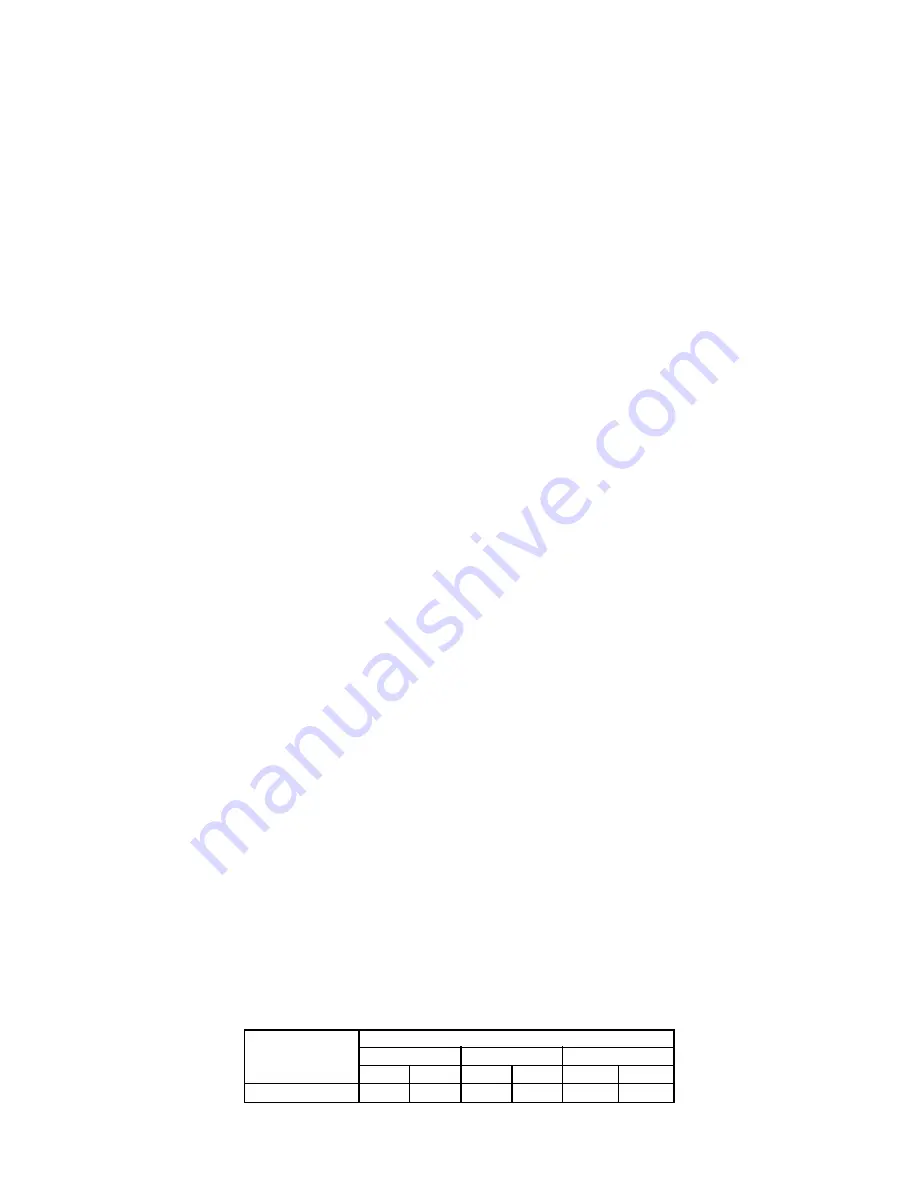
VOLTAGE MONITOR

This device protects the motors in the unit from faults such as; under or over voltage, unbalance & phase reversal of the
power supply. When the device sensed such faults, it will cut-off the supply in the control circuit thereby cutting off power
to the motors. The voltage monitor will re-set automatically when power is brought back to it’s normal conditions.

31

LINE VOLTAGE

RANGE

UNDER VOLTAGE

TRIP

90%

190 - 480 VAC

TRIP & RE-SET VOLTAGE (% OF SET POINT)

OVER VOLTAGE

PHASE IMBALANCE

RE-SET

93%

TRIP

110%

RE-SET

107%

TRIP

6%

RE-SET

4.5%

Содержание CNX150

Страница 1: ...PL OM CNX 07 1M E INSTALLATION OPERATION MAINTENANCE MANUAL AIR COOLED CONDENSING UNITS CNX SERIES...

Страница 2: ...28 Start up inspection check list 28 29 Check out operational start up procedure 29 ELECTRICAL Power supply 30 Unbalanced voltage 30 Motor contactor 31 Fan motor 31 Crankcase heater 31 Lube oil protec...

Страница 3: ...10 GENERATION CODE CNX CONDENSING UNIT 150 220 240 300 360 420 480 540 600 720 840 M00 M10 M20 M40 M60 2M00 2M40 Z SPECIAL OPTIONS F 460 3 60 00 01 02 03 9 MANUFACTURING YEAR 06 07 08 MODEL DECODING...

Страница 4: ...6 HIGH PRESSURE SWITCH Open PSIG 350 10 350 10 350 10 350 10 350 10 350 10 350 10 350 10 350 10 Close PSIG 300 10 300 10 300 10 300 10 300 10 300 10 300 10 300 10 300 10 LOW PRESSURE SWITCH Open PSIG...

Страница 5: ...0 350 10 350 10 350 10 350 10 350 10 350 10 350 10 Close PSIG 300 10 300 10 300 10 300 10 300 10 300 10 300 10 300 10 300 10 LOW PRESSURE SWITCH Open PSIG 10 5 10 5 10 5 10 5 10 5 10 5 10 5 10 5 10 5...

Страница 6: ...0 2 15 9 158 0 86 1 6 4 1 2 45 7 60 2 18 1 187 1 45 2 5 10 0 2 56 1 75 2 22 7 225 1 45 2 5 10 0 2 60 6 80 2 23 6 193 1 45 2 5 10 0 3 70 5 90 2 28 0 220 1 45 2 5 10 0 3 77 5 100 2 30 0 262 1 45 2 5 10...

Страница 7: ...3 73 2 875 37 125 80 0 37 125 2032 A B C 1 2 3 5 4 6 7 5 7 6 4 5 3 2 1 DIMENSIONS NOTES 1 All dimensions are in mm dimensions in brackets are in inches 2 Allow 48 1219 mm clearance on all sides for pr...

Страница 8: ...83 50 1550 61 0 203 8 0 DIMENSIONS CNX 480 CNX 600 CNX 720 CNX 840 NOTES 1 All dimensions are in mm dimensions in brackets are in inches 2 Allow 48 1219 mm clearance on all sides for proper airflow 7...

Страница 9: ...DIMENSIONS CNX M00 CNX M10 NOTES 1 All dimensions are in mm dimensions in brackets are in inches 2 Allow 48 1219 mm clearance on all sides for proper airflow 8...

Страница 10: ...DIMENSIONS CNX M20 NOTES 1 All dimensions are in mm dimensions in brackets are in inches 2 Allow 48 1219 mm clearance on all sides for proper airflow 9...

Страница 11: ...11 220 917 0 36 102 TYP 786 0 30 944 TYP 670 5 26 397 TYP 487 0 19 173 TYP DIMENSIONS CNX M40 NOTES 1 All dimensions are in mm dimensions in brackets are in inches 2 Allow 48 1219 mm clearance on all...

Страница 12: ...YP 786 0 30 944 TYP 670 5 26 397 TYP 487 0 19 173 TYP ELECTRIC POWER INLET DIMENSIONS CNX M60 NOTES 1 All dimensions are in mm dimensions in brackets are in inches 2 Allow 48 1219 mm clearance on all...

Страница 13: ...DIMENSIONS CNX 2M00 NOTES 1 All dimensions are in mm dimensions in brackets are in inches 2 Allow 48 1219 mm clearance on all sides for proper airflow 12...

Страница 14: ...ensions are in mm dimensions in brackets are in inches 2 Allow 48 1219 mm clearance on all sides for proper airflow 13 2185 86 023 275 10 826 2200 86 614 917 0 36 102 TYP 786 0 30 944 TYP 670 5 26 397...

Страница 15: ...LCD Display Information In the normal operating mode the 20 x 4 characters LCD panel displays the system status temperature of leaving returning air and set point if temperature control selected is t...

Страница 16: ...ter to be changed The LCD will show the actual value Using the UP and DOWN keys modify the set point value Press SET to store it or ESC to exit without memorizing COMPRESSOR CONTROL Control setting to...

Страница 17: ...CONNECTION HVTB L2A L1A L3A L3 L1 L2 CB1 L2B L1B L3B CB2 TD1 CLOSED JU10 CLOSED 1 2 2 2 M2 14 L2 R N 2 OLR3 1A 3 FAN MOTOR LAYOUT CNX 360 420 COMPRESSOR POWER CONTROL CONNECTION IN PART WINDING START...

Страница 18: ...OPTIONAL ATB STG2 COOLING OLR2 1A OLR1 1A TO HVTB 10A YR2 1A OPS2 1 SSPS2 YR1 1A P HPS2 JP5B P JP3B 10B 64B 8B JP4B CB2A 1 ATB OPS1 1 SSPS1 HPS1 JP5A JP3A UVM 1 1 JP1 1A 64A 8A JP4A CB1A 1 S1 1B 9A A...

Страница 19: ...103C 104A 105A 103A 105C FM5 37E 35E 36E FM2 37B 36B 35B 103E 104E 105E 105B 104B 103B 2 13F FMC6 T K FM2 FMC2 13B FMC4 T K 13D FM4 36F FM6 FM4 37D 36D 35D 35F 37F 104F 105D 104D 103D 103F 105F TO HV...

Страница 20: ...IG OUT R5 DIG OUT R6 DIG OUT R7 DIG OUT R8 DIG OUT R9 DIG OUT R10 DIG OUT R11 DIG OUT R12 DIG OUT R13 DIG OUT R14 DIG OUT C HTR2 UVM CONNECTION OPTIONAL SH 29A S1 SH A5 SP1 SH DISCHARGE PRESSURE TRANS...

Страница 21: ...DIG OUT R7 DIG OUT R6 DIG OUT R5 DIG OUT R4 DIG OUT R3 DIG OUT R2 DIG OUT R1 DIG OUT TRANS1 75VA YR1 BMR 17 ATB 2 TO ATB Y1 HPS3 OLR3 1A AO4 OLR4 1A YR3 1A YR4 1A HPS4 P 10D 8D JP5D SSPS4 P 10C A19 A...

Страница 22: ...FM14 FMC10 T K 13N 13J FM12 FMC14 FM16 2 FM10 FM12 105N 104N 103N 105J 104J 103J 105O 36J 35J 37O 37N 36N 35N 37J 105P 104P 103P 105L 104L 103L 36P 35P 37L 36L 35L 37P TO HVTB BUSBAR L2 L1 L3 TO HVTB...

Страница 23: ...B REFER FAN MOTOR CONTROL CONNECTION SYSTEM 1 RETURNING AIR TEMP SENSOR PTC 10 50 C 26 SH 27 SH SH 67 52 REFER FAN MOTOR CONTROL CONNECTION SYSTEM 2 3A 3B COMP2 CAPACITY UNLOADER SOLENOID COMP2 PUMP D...

Страница 24: ...FROM THERMOSTAT OR DDC SWITCHING CONTACTS COM LVTB R ATB 15 75VA TRANS1 230V 24V 1 ATB 17 TO ATB 2 SH SH GND ON 1 SERIAL CABLE A10 OP2 O2 DIP S1 X52 2 4 3 SH SH S2 A9 DP2 D2 A8 SP2 TIN 28D SH 30D 31D...

Страница 25: ...TYPICAL HIGH AND LOW VOLTAGE FIELD WIRING CONNECTIONS 24 REMOVE JP7 52 20 1 2 1 67 17 REMOVE JP6 REMOVE JP7...

Страница 26: ...nter of gravity aligns with the main lifting point before lifting Use spreader bar when rigging to prevent the slings from damaging the unit CAUTION All panels should be in place when rigging Care mus...

Страница 27: ...526 526 CNX2M40 822 822 742 742 737 737 732 732 727 727 LOAD DISTRIBUTION kg COPPER CONDENSER COIL 26 MODEL No R1 R2 R3 R4 R5 R6 R7 R8 R9 R10 CNX150 225 225 225 225 CNX220 256 256 256 256 CNX240 270...

Страница 28: ...tric power 5 Position the unit to provide for unrestricted air circulation and to prevent any possibility of air recirculation 6 Check minimum clearances required for your unit with regard to walls or...

Страница 29: ...ation is completed in all respect the following points should be covered before the system is switched on for operation 1 Remove or loosen shipping retainers under motor compressors Make sure the hold...

Страница 30: ...quate lubrication in order to provide some allowance for oil which will be circulating in the system during operation Depending on the system design the amount of oil in the system at the time of comp...

Страница 31: ...lanced voltage on a three phase compressor motor may overheat and trip the motor on external or internal current sensing motor protector whichever one is provided To determine that an unbalanced volta...

Страница 32: ...lubrication at the bearings furthest from the oil pump The center and rear bearings may seize or may wear enough to allow the rotor to drop and drag on the stator causing it to short Also the liquid r...

Страница 33: ...slider control valve for capacity unloading suction discharge shut off valves check valve in discharge gas outlet oil sight glass oil fill drain service valve directly flanged on three stage oil separ...

Страница 34: ...rs 8 Take an oil sample and test for acidity If the first acidity test shows that the acid content is below the safe level as indicated in the test kit instructions and the oil is clean the clean out...

Страница 35: ...oth cut out and cut in pressure within 2 psig PUMP DOWN CONTROL A pump down control is a solenoid type valve installed in the liquid line to prevent the flow of refrigerant into the evapo rator during...

Страница 36: ...r 4 Check airflow across the condenser coil restrictions in refrigeration sys tem 5 Check for possibility of misapplica tion Use stronger unit 6 Check refrigerant charge fix leak add if necessary 7 Re...

Страница 37: ...rect 4 Replace with larger system 5 Defrost 6 Determine location and remove 7 Clean condenser 8 Clean or replace 1 Correct the refrigerant charge 2 Recharge the system after a thorough triple evacuati...

Страница 38: ...sion valve and other possible causes like clogged filter low CFM iced evaporator etc and correct it 2 Check the system for correct super heat and other possible causes like clogged filter low CFM iced...

Страница 39: ...80064658 80064658 80064658 80064658 80064658 80064658 80064658 80064658 80064658 38 MODEL NUMBER CNX720F CNX840F CNXM00F CNXM10F CNXM20F CNXM40F CNXM60F CNX2M00F CNX2M40F COMPRESSOR 80069732 80069732...

Страница 40: ...2 Contactor compressor 2 1 3 2 Contactor fan motors 2 1 3 2 HPS Sensor Transducer 2 1 3 2 Expansion valve 1 0 5 2 1 Filter drier 2 1 3 2 Transformer 24V secondary 1 0 5 2 1 Propeller fan 1 0 5 2 1 Hea...

Страница 41: ...damaged body parts repair repaint as necessary Check mountings spring isolator rubber pads Repair replace as necessary Check flexible canvas connections duct work Repair replace as required Run test...

Страница 42: ...hese are toxic Decomposition Products and corrosive General Precautions Avoid inhalation of high concentrations of vapors Atmospheric concentrations should be minimized and kept as low as possible The...

Страница 43: ...3 33 329 6 228 2 40 49 7 35 0 4 44 342 6 241 3 42 51 6 36 9 5 56 356 1 254 8 44 53 7 39 0 6 67 370 0 268 7 46 55 7 41 0 7 78 384 3 283 0 48 57 9 43 2 8 89 399 0 297 7 50 60 0 45 4 10 00 414 1 312 8 5...

Страница 44: ...4 1251 1 126 201 6 186 9 52 22 1390 3 1288 9 128 207 2 192 5 53 33 1428 9 1327 6 130 212 9 198 2 54 44 1468 4 1367 1 132 218 8 204 1 55 56 1508 7 1407 4 134 224 7 210 0 56 67 1549 8 1448 5 136 230 8...

Отзывы: