User’s Manual
133
I
NDEX
A
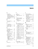
A/D converter
buffered inputs .................. 30
calibration constants ......... 31
differential measurements . 31
single-ended measurements 31
voltage ranges ................... 30
analog inputs ......................... 30
B
battery connections ............. 121
battery tab ......................... 13
C
CE compliance ........................ 6
design guidelines ................. 7
chip select circuit ................ 123
conformal coating ................. 73
D
digital inputs ......................... 22
switching threshold ........... 22
digital outputs ....................... 23
dimensions
LCD/keypad template ....... 88
LP3500 .............................. 68
plastic enclosure .............. 118
Prototyping Board ............. 82
Dynamic C ........................ 5, 35
add-on modules ............. 5, 36
debugging features ............ 35
installation ......................... 14
starting .............................. 14
telephone-based technical
support ...................... 5, 36
upgrades and patches ........ 36
E
exclusion zone ...................... 71
F
features .................................... 2
flash memory
lifetime write cycles .......... 35
I
I/O address assignments
LCD/keypad module ......... 89
installation
plastic enclosure
LP3500 ........................ 116
J
jumper configurations ..... 74, 75
current measurement
options) ......................... 75
select) ............................ 75
lect) ......................... 34, 75
select) ............................ 75
select) ............................ 75
select) ............................ 75
select) ............................ 75
select) ............................ 75
JP7 (SRAM size) .............. 75
JP8 (flash memory size) .... 75
JP9 (flash memory size) .... 75
jumper locations ................ 74
K
keypad template .................... 88
bel ................................. 88
L
LCD/keypad module ............... 3
bezel-mount installation .... 90
dimensions ........................ 86
header pinout .................... 89
I/O address assignments ... 89
keypad template ................ 88
model options .................... 85
removing and inserting keypad
label .............................. 88
sample programs ............. 113
voltage settings ................. 87
M
memory ................................. 34
tions .............................. 34
different sizes ............... 34
models ..................................... 2
LP3500 ................................ 2
LP3510 ................................ 2
O
options .................................... 3
P
pinout
LCD/keypad module ......... 89
LP3500 headers ................ 18
programming port ........... 126
plastic enclosure ............. 3, 115
assembly instructions ...... 116
dimensions ...................... 118
mounting instructions ..... 117
setup
Содержание Fox LP3500
Страница 1: ...Fox LP3500 C Programmable Single Board Computer User s Manual 019 0111 041029 E ...
Страница 6: ...Fox LP3500 ...
Страница 14: ...8 Fox LP3500 ...
Страница 22: ...16 Fox LP3500 ...
Страница 86: ...80 Fox LP3500 ...
Страница 120: ...114 Fox LP3500 ...
Страница 130: ...124 Fox LP3500 ...
Страница 134: ...128 Fox LP3500 ...
Страница 138: ...132 Fox LP3500 ...
Страница 142: ...136 Fox LP3500 ...
Страница 144: ......

