User’s Manual
119
A
PPENDIX
E. P
OWER
M
ANAGEMENT
Appendix E describes the power circuitry provided on the
LP3500. The LP3500 can operate from an unregulated external
power source, or from an external battery. There is onboard bat-
tery backup for the SRAM and the real-time clock.
E.1 External Power Supply
Power is normally supplied to the LP3500 via pins 16 and 17 of header J2 on the LP3500.
The Prototyping Board provides a convenient header plug for use with the AC adapter
included with the LP3500 Tool Kit. The Prototyping Board includes a Shottky diode for
protection against reverse polarity.
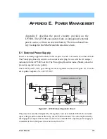
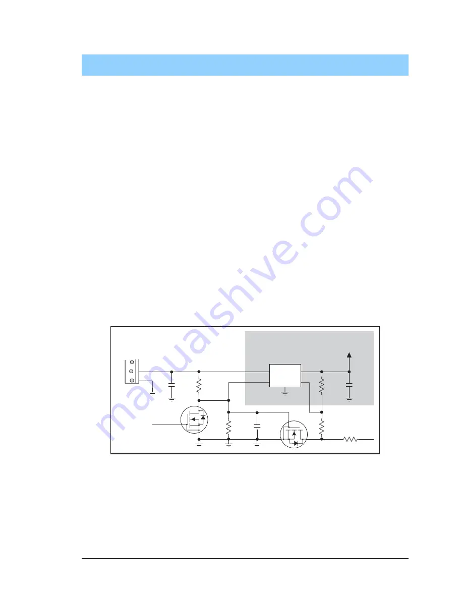
The raw DC power, VIN, goes through a linear regulator as shown in Figure E-1. The lin-
ear regulator outputs a Vcc of 2.8 V DC.
Figure E-1. LP3500 Linear Regulator Circuit
The power necessarily dissipated by the regulator can be calculated if both the external
input voltage and the current drawn by the LP3500 are known. The current provided by
the high-power output drivers does not have to be included if a separate power supply is
connected to K so that power does not come from Vcc.
LINEAR POWER SUPPLY
J2
47 µF
10 µF
VIN
Vcc
C64
C65
16
17
105 k
W
R51
MIC5236
U13
2
3
PF7
Q20
PB0
R57
220 k
W
R53
20 k
W
26.1 k
W
R52
Q18
100 nF
220 k
W
C70
R58
4
1
Содержание Fox LP3500
Страница 1: ...Fox LP3500 C Programmable Single Board Computer User s Manual 019 0111 041029 E ...
Страница 6: ...Fox LP3500 ...
Страница 14: ...8 Fox LP3500 ...
Страница 22: ...16 Fox LP3500 ...
Страница 86: ...80 Fox LP3500 ...
Страница 120: ...114 Fox LP3500 ...
Страница 130: ...124 Fox LP3500 ...
Страница 134: ...128 Fox LP3500 ...
Страница 138: ...132 Fox LP3500 ...
Страница 142: ...136 Fox LP3500 ...
Страница 144: ......


