User’s Manual
9
2. G
ETTING
S
TARTED
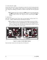
Chapter 2 explains how to connect the programming cable and
power supply to the LP3500.
2.1 LP3500 Connections
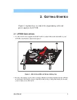
1. Use the 4-40 screws supplied with the Tool Kit to attach the metal stand-offs to your
LP3500 series board as shown in Figure 2.
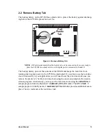
Figure 2. Attach Stand-Offs and Remove Battery Cap
2. Remove the battery cap from the coin-type lithium-ion battery installed on the LP3500
series board. The battery cap was inserted in the factory to keep the battery fresh until
you are ready to use the board.
C44
C43
C59
C60
U9
R16
R13
C10
C13
R17
R18
C16
C19
C36
U1
C70
R51
R58
C65
C26
C33
R20
R25
R22
R26
R29
C37
R32
C40
Y1
D22
C50 R36
R40 C54
R37
C24
R30
D19
D20
D21
D18
D25
Q5
R42
Q6
R43
R33
Q8
Q10
D26
D28
Q16
D30
Q17
D34
K1
Q13
D32
D33
Q14
J6
C67
C55 R44
R47
U11
S1
RESET
J5
J2
PROGRAM
PORT
AIN0 AIN1
A
I
N2
AIN3 AIN4 AIN5 AIN6 AIN7 GND
GND VBAT
EXT GND VIN GND
PWM
0
PWM
1
PWM
2
GND
DIS
PL
AY
R55
R56
J9
J8
RELAY
NO
CO
M
NC
C48
U3
R57
R31
C29
R23
C22
C20
C12
C15
D15
D17
RP1
7
D13
BT1
D11
D5
D7
D2
D4
C8
C6
D8
D1
AIN0 AIN1 AIN2 AIN3
J3
R1
C3
C2
R6
R7
R9
Q22
RN1
RN2
R54
RP1
4
RP13
Q20
U13
C64
R50
R49
Y2
C61
Q12
R45
R34
U8
C51
R39
R41
C53
R38
R48
C6
6
U12
U10
GND
+K GND 485 + GND TxB RxB GND
TxC RxC GND TxE RxE GND
J4
J1
OUT
9
OUT
8
OUT
7
OUT
6
OUT
5
OUT
4
OUT
3
OUT
2
OUT
0
OUT
1
IN00
IN
01 IN
02 IN
03 IN
04 IN
05 IN
06 IN
07
G
ND
IN08
IN
09 IN
10 IN
11 IN
12 IN
13 IN
14 IN
15
Battery
Содержание Fox LP3500
Страница 1: ...Fox LP3500 C Programmable Single Board Computer User s Manual 019 0111 041029 E ...
Страница 6: ...Fox LP3500 ...
Страница 14: ...8 Fox LP3500 ...
Страница 22: ...16 Fox LP3500 ...
Страница 86: ...80 Fox LP3500 ...
Страница 120: ...114 Fox LP3500 ...
Страница 130: ...124 Fox LP3500 ...
Страница 134: ...128 Fox LP3500 ...
Страница 138: ...132 Fox LP3500 ...
Страница 142: ...136 Fox LP3500 ...
Страница 144: ......


