24
Fox (LP3500)
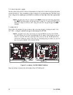
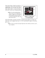
When the LP3500 is connected to the Proto-
typing Board, a 0
Ω
resistor on the Prototyp-
ing Board (R1) ties +K to VIN, the raw DC
input voltage. Figure 12 shows the location
of this 0
Ω
resistor on the Prototyping Board.
NOTE:
R1 on the Prototyping Broad
must be removed to avoid damage to
the power supplies
if
you are using the
Prototyping Board with the LP3500
and
you are using separate power sup-
plies for VIN and K.
When the LP3500 is used alone, remember to connect a power supply to +K (pin 12 on
header J7). Your +K supply may be up to +36 V DC, and should be capable of delivering
up to 2.0 A.
NOTE:
If +K is not connected, the digital inputs may float, which may increase your cur-
rent consumption.
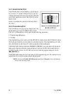
Figure 12. Location of R1
on Prototyping Board
OUT8 OUT7 OUT6 OUT5 OUT4 OUT3 OUT2 OUT1 OUT0
J44
GND
VIN
DS4 DS3 DS2 DS1
D1
PWR
J5
R1
R1
Содержание Fox LP3500
Страница 1: ...Fox LP3500 C Programmable Single Board Computer User s Manual 019 0111 041029 E ...
Страница 6: ...Fox LP3500 ...
Страница 14: ...8 Fox LP3500 ...
Страница 22: ...16 Fox LP3500 ...
Страница 86: ...80 Fox LP3500 ...
Страница 120: ...114 Fox LP3500 ...
Страница 130: ...124 Fox LP3500 ...
Страница 134: ...128 Fox LP3500 ...
Страница 138: ...132 Fox LP3500 ...
Страница 142: ...136 Fox LP3500 ...
Страница 144: ......

