JOHNSON CONTROLS
12
FORM 160.69-O1
ISSUE DATE: 9/30/2012
SECTION 1 – DESCRIPTION OF SYSTEM AND FUNDAMENTALS OF OPERATION
SECTION 1 – DESCRIPTION OF SYSTEM AND FUNDAMENTALS OF OPERATION
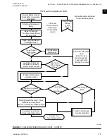
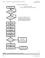
An LED on the Surge – Dual Compressor Setup Screen
and the Capacity Compressor Cycling Screen illumi-
nates whenever a high head Lag compressor start con-
dition exists. Also, “Warning – Head Pressure – High
Head Lag Start Limit” is displayed on the System Sta-
tus line of the Display during this condition.
Condenser Refrigerant Level Control – Lag
Start
(Software version C.MLM.11.02.xxx and later or
C.OPT.11.02.300 and later)
When operating at low condenser liquid temperatures,
a Low Evaporator Pressure trip can occur when going
from one to two compressor operation.
During startup of the Lag compressor, as the Lag Dis-
charge Valve opens, the system will see a step change
in refrigerant flow. Although the Condenser Refrig-
erant Level Control keeps the refrigerant level stable
during normal operation, the variable orifice does not
open quickly enough when the Lag compressor is
started. This causes the refrigerant to stack in the in
the condenser, starving the evaporator, and causing a
low evaporator pressure shutdown.
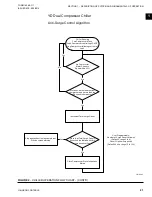
The condenser Refrigerant Level Control Lag Start
mode is initiated when the Lag compressor enters
Prelube and is terminated 2 minutes after the Lag Dis-
charge Valve has opened. During this mode, if the re-
frigerant level is > 20%, the level control lower (valve
open) output is turned on for 5 seconds every 10 sec-
onds until the level is less than 20%. If the refrigerant
level is < 20%, the level control is held in place.
After the Lag Start mode has ended, a linearly increas-
ing ramp limit, called the Refrigerant Level Target,
is applied to the REFRIGERANT LEVEL setpoint.
This ramp allows the level to go from the present level
(20%) to the programmed Refrigerant Level Setpoint
over a period equal to one-half of the VALVE PRESET
TIME setpoint. During this ramp-up period, the Re-
frigerant Level target is used to control the refrigerant
level in the condenser. The Refrigerant Level Setpoint
is then used to control the level for the remainder of
the run period.
On the Refrigerant Level Control Screen, the Refriger-
ant Level Override Mode displays “Valve Preset” dur-
ing the pre-positioning of the Refrigerant Level Con-
trol Valve while bringing on the Lead compressor. It
displays “Lag Start” when performing the Refrigerant
Level Control Lag Start mode while starting the Lag
compressor. The Override Time Remaining displays
the time remaining in the “Valve Preset” mode or the
time remaining in the “Lag Start” mode. In the first
case, it is the time remaining in the Valve Preset Timer
plus the time remaining of the first 3 minutes of Lead
compressor run time. In the second case, it is the time
remaining in the Lag compressor Pre-lube cycle plus
the time remaining in the first 3.5 minutes of Lag com-
pressor run time.
There are different methods of compressor motor cur-
rent limit used, depending on the Controls Software
version as follows:
Current Limit (Software version C.OPT.11.02B.xxx
(and earlier)):
Upon entering “System Run”, the total of both com-
pressor’s motor current will be limited to the value
programmed for the
Chiller Pulldown Demand Lim-
it
Setpoint (30% to 100% FLA) as long as the Chiller
Pulldown Period is in effect (it is in effect until the
Leaving Chilled Liquid Temperature is within 2º F of
the Leaving Chilled Liquid Temperature setpoint).
After the Chiller Pulldown Period is no longer in ef-
fect, the Chiller Steady State Period begins and is in
effect until the chiller is shutdown. During this period,
the total of both compressor’s motor current will be
limited to the value programmed for the
Chiller Cur-
rent Limit
Setpoint (30% to 100% FLA).
Both the above setpoints are applied to the total chiller
current (total of both compressor’s motor current). For
example, if the Chiller FLA is 1600 Amps, the FLA
of each motor is 800 Amps. If either setpoint is set
to 70%, the Chiller Current would be limited to 1120
Amps. If both compressors are running, each would be
limited to 560 amps. If only one motor is running, the
motor would be allowed to operate all the way up to its
full load amps of 800 Amps, because the total chiller
current is being limited to 1120 Amps.
Current Limit (Software version C.OPT.11.03.01.004
(and later)):
The
Lead Compressor Pulldown Time
Setpoint can
be used to limit the chiller to single compressor op-
eration for a specified duration (0-255 minutes) when
starting the chiller. While this pulldown time is in ef-
fect, “System In Lead Compressor Pulldown” is dis-
played on the System Details line along with the time
remaining in the period. During this time, only the
lead compressor is permitted to run. The lag compres-


