JOHNSON CONTROLS
51
SECTION 2 – OPTIVIEW CONTROL CENTER
FORM 160.69-O1
ISSUE DATE: 9/30/2012
2
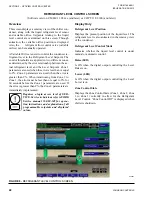
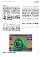
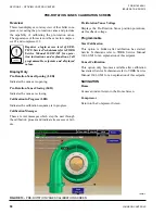
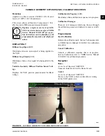
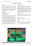
VARIABLE GEOMETRY DIFFUSER (VGD) 1 SCREEN
Overview
(This feature applies to Software version C.MLM.11.02.
XXX (and later) or C.OPT.11.02.300 (and later))
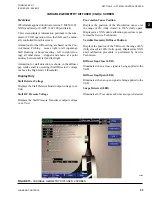
This screen displays information pertinent to the com-
pressor 1 VGD operation. Also, the VGD can be manu-
ally controlled from this screen.
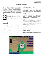
Animations for the diffuser ring are based on the Con-
trol Status: Probing – moves right to left (opening),
Stall Reacting or Surge reacting – left to right (clos-
ing), all other states – stopped and shown at a point
midway between full left and full right.
Animation for stall detection is shown in the diffuser
gap while a stall is occurring (Stall Detector 1 voltage
is above the High Limit 1 threshold).
Display Only
Stall Detector Voltage
Displays the Stall Detector Board output voltage
(x.xxVdc).
Stall DC Pressure Voltage
Displays the Stall Pressure Transducer output voltage
(x.xx Vdc)
Pre-rotation Vanes Position
Displays the position of the Pre-rotation vanes over
the range of 0% (fully closed) to 100% (fully open).
Displayed as XXX until calibration procedure is per-
formed by Service Technician.
Variable Geometry Diffuser Position
Displays the position of the VDG over the range of 0%
(fully closed) to 100% (fully open). Displayed as XXX
until calibration procedure is performed by Service
Technician.
Diffuser Gap Close (LED)
Illuminates when a close signal is being applied to the
VGD.
Diffuser Gap Open (LED)
Illuminates when an open signal is being applied to the
VGD.
Surge Detected (LED)
Illuminates for 5 seconds each time a surge is detected.
FIGURE 14 -
VARIABLE GEOMETRY DIFFUSER 1 SCREEN
50038

