


JOHNSON CONTROLS
43
SECTION 6 – MAINTENANCE
FORM 160.69-O2
ISSUE DATE: 9/30/2020
6
CHECKING THE REFRIGERANT CHARGE
DURING UNIT SHUTDOWN
The refrigerant charge is specified for each chiller
model (See
). Charge the correct
amount of refrigerant and record the level in the evapo-
rator sight glass.
The refrigerant charge should always be checked and
trimmed when the system is shut down.
The refrigerant charge level must be checked after the
pressure and temperature have equalized between the
condenser and evaporator. This would be expected
to be 4 hours or more after the compressor and water
pumps are stopped. The level should visible in the sight
glass.
Charge the refrigerant in accordance with the method
shown under the “Refrigerant Charging”, above. The
refrigerant level should be observed and the level re-
corded after initial charging.
HANDLING REFRIGERANT FOR
DISMANTLING AND REPAIRS
If it becomes necessary to open any part of the refriger-
ant system for repairs, it will be necessary to remove
the charge before opening any part of the unit. If the
chiller is equipped with optional valves, the refrigerant
can be isolated in either the condenser or evaporator /
compressor while making any necessary repairs.
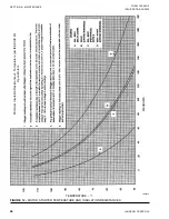
MEGGING THE MOTOR
While the main disconnect switch and compressor mo-
tor starter are open, meg the motor as follows:
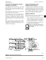
1. Using a megohm meter (megger), meg between
phases and each phase to ground (See
Figure 11
on page 43
); these readings are to be interpreted
using the graph shown in
.
2. If readings fall below shaded area, remove exter-
nal leads from motor and repeat test.
Motor is to be megged with the starter at
ambient temperature after 24 hours of
idle standby.
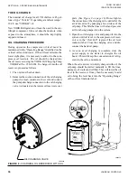
FIGURE 11 -
MEGGING MOTOR WINDINGS
LD00475
Содержание YD A
Страница 8: ...JOHNSON CONTROLS 8 FORM 160 69 O2 ISSUE DATE 9 30 2020 THIS PAGE INTENTIONALLY LEFT BLANK...
Страница 22: ...JOHNSON CONTROLS 22 FORM 160 69 O2 ISSUE DATE 9 30 2020 THIS PAGE INTENTIONALLY LEFT BLANK...
Страница 28: ...JOHNSON CONTROLS 28 FORM 160 69 O2 ISSUE DATE 9 30 2020 THIS PAGE INTENTIONALLY LEFT BLANK...
Страница 34: ...JOHNSON CONTROLS 34 FORM 160 69 O2 ISSUE DATE 9 30 2020 THIS PAGE INTENTIONALLY LEFT BLANK...
Страница 48: ...JOHNSON CONTROLS 48 FORM 160 69 O2 ISSUE DATE 9 30 2020 THIS PAGE INTENTIONALLY LEFT BLANK...