


JOHNSON CONTROLS
39
FORM 160.69-O2
ISSUE DATE: 9/30/2020
6
SECTION 6 – MAINTENANCE
CHECKING SYSTEM FOR LEAKS
Leak Testing During Operation
The refrigerant side of the system is carefully pressure
tested and evacuated at the factory.
After the system has been charged, the system should
be carefully leak tested with a R-134a compatible leak
detector to be sure all joints are tight.
If any leaks are indicated, they must be repaired im-
mediately. Usually, leaks can be stopped by tighten-
ing flare nuts or flange bolts. However, for any major
repair, the refrigerant charge must be removed. (See
“Handling Refrigerant for Dismantling and Repair”)
CONDUCTING R-22 PRESSURE TEST
With the R-134a charge removed and all known leaks
repaired, the system should be charged with a small
amount of R-22 mixed with dry nitrogen so that a ha-
lide torch or electronic leak detector can be used to de-
tect any leaks too small to be found by the soap test.
To test with R-22, proceed as follows:
1. With no pressure in the system, charge R-22 gas
into the system through the charging valve to a
pressure of 2 PSIG (14 kPa).
2. Build up the system pressure with dry nitrogen to
approximately 75 to 100 PSIG (517 to 690 kPa).
To be sure that the concentration of refrigerant has
reached all part of the system, slightly open the oil
charging valve and test for the presence of refrig-
erant with a leak detector.
3. Test around each joint and factory weld. It is im-
portant that this test be thoroughly and carefully
done, spending as much time as necessary and us-
ing a good leak detector.
4. To check for refrigerant leaks in the evaporator
and condenser, open the vents in the evaporator
and condenser heads and test for the presence of
refrigerant. If no refrigerant is present, the tubes
and tube sheets may be considered tight. If refrig-
erant is detected at the vents, the heads must be
removed, the leak located (by means of soap test
or leak detector) and repaired.
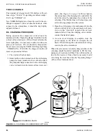
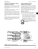
FIGURE 9 -
EVACUATION OF CHILLER
27385A(D)
LD00949
Содержание YD A
Страница 8: ...JOHNSON CONTROLS 8 FORM 160 69 O2 ISSUE DATE 9 30 2020 THIS PAGE INTENTIONALLY LEFT BLANK...
Страница 22: ...JOHNSON CONTROLS 22 FORM 160 69 O2 ISSUE DATE 9 30 2020 THIS PAGE INTENTIONALLY LEFT BLANK...
Страница 28: ...JOHNSON CONTROLS 28 FORM 160 69 O2 ISSUE DATE 9 30 2020 THIS PAGE INTENTIONALLY LEFT BLANK...
Страница 34: ...JOHNSON CONTROLS 34 FORM 160 69 O2 ISSUE DATE 9 30 2020 THIS PAGE INTENTIONALLY LEFT BLANK...
Страница 48: ...JOHNSON CONTROLS 48 FORM 160 69 O2 ISSUE DATE 9 30 2020 THIS PAGE INTENTIONALLY LEFT BLANK...