YORK INTERNATIONAL
83
FORM 150.62-NM1
Condenser fans are controlled by ambient tem
pera-
t
ure and discharge pressure. This mode must be cho-
sen if the discharge pressure transducers are not in-
stalled, or if the fan cycling is a concern.
Option 11 – Manual Override Mode
T
his option allows overriding of the daily schedule that
is programmed. MANUAL OVERRIDE MODE-DISABLED
indicates that override mode has no effect.
or
Manual Override Mode is enabled. This is a service func-
tion and when enabled, will allow the unit to start when
shut down on the daily schedule. It will automatically be
disabled after 30 minutes.
CLOCK
The CLOCK display shows the current day, time, and
date. Pressing the CLOCK key will show the current
day, time, and date.
It is important that the date and time be correct, other-
wise the daily schedule will not function as desired if
programmed. In addition, for ease of troubleshooting
via the History printouts, the day, time, and date should
be correct.
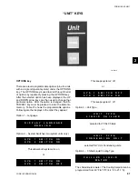
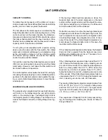
To change the day, time, and date press the CLOCK
key. The display will show something similar to the fol-
lowing:
The line under the F is the cursor. If the day is correct,
press the ENTER/ADV key. The cursor will move under
the 0 in 08 hours. If the day is incorrect, press the UP or
DOWN
arrow keys until the desired day is displayed
and then press the ENTER/ADV key at which time the
day will be accepted and the cursor will move under the
0. In a similar manner, the hour, minute, meridian, month,
day, and year may be programmed, whenever the cur-
sor is under the first letter/numeral of the
item.
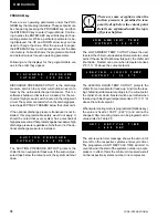
Jumper J11 on the microboard must
be set to the “CLKON” position to turn
on the clock. If this is not done the
clock will not function.
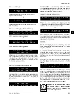
Option 8 – Units Type
Display messages will show units of measure in
Imperial units (°F or PSI).
or
Display messages will show units of measure in SI
units (°C or Bar).
Option 9 – Lead/Lag Type (two systems only)
SYS 1 selected as lead compressor.
or
SYS 2 selected as lead compressor.
or
In this mode the micro determines which system is as-
signed to the lead and lag. A new lead/lag assignment
is made whenever all compressors shut down. The mi-
cro will then assign the “lead” to the compressor with
the shortest average run time.
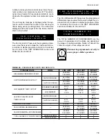
Option 10 – Condensed Fan Control Mode
Condenser fans are controlled by discharge pressure
only. This mode may only be chosen when discharge
pressure transducers are installed, or if fan cycling is
not a concern.
or
D I S P L A Y
U N I T S
I M P E R I A L
D I S P L A Y
U N I T S
S I
L E A D / L A G
C O N T R O L
M A N U A L
S Y S
1
L E A D
L E A D / L A G
C O N T R O L
A U T O M A T I C
L E A D / L A G
C O N T R O L
M A N U A L
S Y S
2
L E A D
M A N U A L
O V E R R I D E
M O D E
D I S A B L E D
F A N
C O N T R O L
D I S C H A R G E
P R E S S U R E
F A N
C O N T R O L
A M B I E N T
&
D S C H
P R E S S
M A N U A L
O V E R R I D E
M O D E
E N A B L E D
T O D A Y
I S
F R I
0 8 : 5 1 A M
1
M A Y
9 8
2
Содержание YCAL0080SC
Страница 112: ...YORK INTERNATIONAL 112 ELEMENTARY DIAGRAM YCAL0014SC YCAL0030SC FIG 11 ELEMENTARY DIAGRAM Wiring Diagrams...
Страница 114: ...YORK INTERNATIONAL 114 ELEMENTARY DIAGRAM YCAL0014SC YCAL0030SC LD03532 FIG 12 ELEMENTARY DIAGRAM Wiring Diagrams...
Страница 115: ...YORK INTERNATIONAL 115 FORM 150 62 NM1 This page intentionally left blank 4...
Страница 116: ...YORK INTERNATIONAL 116 ELEMENTARY DIAGRAM YCAL0034SC FIG 13 ELEMENTARY DIAGRAM Wiring Diagrams...
Страница 117: ...YORK INTERNATIONAL 117 FORM 150 62 NM1 FIG 13 ELEMENTARY DIAGRAM Cont d LD03533 ELEMENTARY DIAGRAM YCAL0034SC 4...
Страница 118: ...YORK INTERNATIONAL 118 FIG 14 ELEMENTARY DIAGRAM ELEMENTARY DIAGRAM YCAL0034SC LD03534 Wiring Diagrams...
Страница 119: ...YORK INTERNATIONAL 119 FORM 150 62 NM1 This page intentionally left blank 4...
Страница 120: ...YORK INTERNATIONAL 120 ELEMENTARY DIAGRAM YCAL0040SC YCAL0060SC FIG 15 ELEMENTARY DIAGRAM Wiring Diagrams...
Страница 122: ...YORK INTERNATIONAL 122 ELEMENTARY DIAGRAM YCAL0040SC YCAL0060SC FIG 16 ELEMENTARY DIAGRAM Wiring Diagrams...
Страница 124: ...YORK INTERNATIONAL 124 ELEMENTARY DIAGRAM YCAL0064SC YCAL0080SC FIG 17 ELEMENTARY DIAGRAM Wiring Diagrams...
Страница 126: ...YORK INTERNATIONAL 126 ELEMENTARY DIAGRAM YCAL0064SC YCAL0080SC FIG 18 ELEMENTARY DIAGRAM Wiring Diagrams...
Страница 130: ...APPENDIX 1 DIMENSIONS FIG 19 TYPE CP 1 FIG 20 TYPE CP 2 LD03839 LD03840 Appendix 1 Isolators...
Страница 135: ...YORK INTERNATIONAL 135 FORM 150 62 NM1 This page intentionally left blank...


