YORK INTERNATIONAL
64
Restart is allowed after the unit is fully powered again
and the anti-recycle timers have finished counting down.
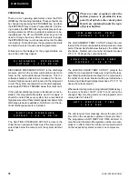
UNIT WARNING
The following message is not a unit safety and will not
be logged to the history buffer. It is a
unit warning and
will not auto-restart. Operator intervention is required
to allow a re-start of the chiller.
The Low Battery Warning can only occur at unit power-
up. On micro panel power-up, the RTC battery is
checked. If a low battery is found, all programmed
setpoints, program values, options, time, schedule, and
history buffers will be lost. These values will all be reset
to their default values which may not be the desired
operating values. Once a faulty battery is detected, the
unit will be prevented from running until the PROGRAM
key is pressed. Once PROGRAM is pressed the anti-
recycle timers will be set to the programmed anti-re-
cycle time to allow the operator time to check setpoints,
program values, and options.
If a low battery is detected, it should be replaced as
soon as possible. The programmed values will all be
lost and the unit will be prevented from running on the
next power interruption. The RTC/battery is located at
U17 on the microboard.
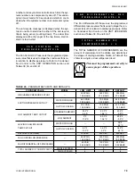
The Low Ambient Temp Cutout is a safety shutdown
designed to protect the chiller from operating in a low
ambient condition. If the outdoor ambient temperature
falls below the programmable cutout, the chiller will shut
down. Restart can occur when temperature rises 2°F
above the cutoff.
The Low Leaving Chilled Liquid Temp Cutout protects
the chiller form an evaporator freeze-up should the
chilled liquid temperature drop below the freeze point.
This situation could occur under low flow conditions or
if the micro panel setpoint values are improperly pro-
grammed. Anytime the leaving chilled liquid tempera-
ture (water or glycol) drops below the cutout point, the
chiller will shutdown. Restart can occur when chilled
liquid temperature rises 2°F above the cutout.
The Under Voltage Safety assures that the system is
not operated at voltages where malfunction of the mi-
croprocessor could result in system damage. When
the115VAC to the micro panel drops below a certain
level, a unit fault is initiated to safely shut down the unit.
U N I T
F A U L T :
L O W
A M B I E N T
T E M P
U N I T
F A U L T :
1 1 5 V A C
U N D E R
V O L T A G E
U N I T
F A U L T :
L O W
L I Q U I D
T E M P
! !
L O W
B A T T E R Y
! !
C H E C K
P R O G / S E T P / O P T N
Unit Controls
Содержание YCAL0080SC
Страница 112: ...YORK INTERNATIONAL 112 ELEMENTARY DIAGRAM YCAL0014SC YCAL0030SC FIG 11 ELEMENTARY DIAGRAM Wiring Diagrams...
Страница 114: ...YORK INTERNATIONAL 114 ELEMENTARY DIAGRAM YCAL0014SC YCAL0030SC LD03532 FIG 12 ELEMENTARY DIAGRAM Wiring Diagrams...
Страница 115: ...YORK INTERNATIONAL 115 FORM 150 62 NM1 This page intentionally left blank 4...
Страница 116: ...YORK INTERNATIONAL 116 ELEMENTARY DIAGRAM YCAL0034SC FIG 13 ELEMENTARY DIAGRAM Wiring Diagrams...
Страница 117: ...YORK INTERNATIONAL 117 FORM 150 62 NM1 FIG 13 ELEMENTARY DIAGRAM Cont d LD03533 ELEMENTARY DIAGRAM YCAL0034SC 4...
Страница 118: ...YORK INTERNATIONAL 118 FIG 14 ELEMENTARY DIAGRAM ELEMENTARY DIAGRAM YCAL0034SC LD03534 Wiring Diagrams...
Страница 119: ...YORK INTERNATIONAL 119 FORM 150 62 NM1 This page intentionally left blank 4...
Страница 120: ...YORK INTERNATIONAL 120 ELEMENTARY DIAGRAM YCAL0040SC YCAL0060SC FIG 15 ELEMENTARY DIAGRAM Wiring Diagrams...
Страница 122: ...YORK INTERNATIONAL 122 ELEMENTARY DIAGRAM YCAL0040SC YCAL0060SC FIG 16 ELEMENTARY DIAGRAM Wiring Diagrams...
Страница 124: ...YORK INTERNATIONAL 124 ELEMENTARY DIAGRAM YCAL0064SC YCAL0080SC FIG 17 ELEMENTARY DIAGRAM Wiring Diagrams...
Страница 126: ...YORK INTERNATIONAL 126 ELEMENTARY DIAGRAM YCAL0064SC YCAL0080SC FIG 18 ELEMENTARY DIAGRAM Wiring Diagrams...
Страница 130: ...APPENDIX 1 DIMENSIONS FIG 19 TYPE CP 1 FIG 20 TYPE CP 2 LD03839 LD03840 Appendix 1 Isolators...
Страница 135: ...YORK INTERNATIONAL 135 FORM 150 62 NM1 This page intentionally left blank...


