


211
JOHNSON CONTROLS
SECTION 9 – SERVICE AND TROUBLESHOOTING
FORM 150.67-NM1
ISSUE DATE: 4/28/2017
9
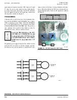
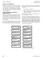
OPTIONAL PRINTER INSTALLATION
The micro panel is capable of supplying a printout
of chiller conditions or fault shutdown information at
any given time. This allows operator and service per-
sonnel to obtain data and system status with the touch
of the keypad. In addition to manual print selection,
the micro panel will provide an automatic printout
whenever a fault occurs. Detailed explanation of the
print function is given under PRINT key located in
the Keypad and Display section.
YORK recommends the field tested WEIGH-TRONIX
model 1220 printer (or former IMP 24). This is a com-
pact low cost printer that is ideal for service work and
data logging.
The WEIGH-TRONIX printer can be obtained by con-
tacting WEIGH-TRONIX for purchase information at:
WEIGH-TRONIX
2320 Airport Blvd.
Santa Rosa, CA 95402
Phone: 1-800-982-6622 or 1-707-527-5555
(International Orders Only)
The part number for the printer that is packaged spe-
cifically for YORK is P/N 950915576. The cable to
connect the printer can either be locally assembled
from the parts listed, or ordered directly from WEIGH-
TRONIX under part number 287-040018.
Parts
The following parts are required:
1. WEIGH-TRONIX model 1220 printer.
2. Wide desk top calculator paper, 2.25" (5.7cm).
3. Twisted Pair Shielded Cable (minimum 3 conduc-
tor), #18 AWG stranded, 300V minimum insula-
tion, 25 ft. (7.62m) maximum length.
4. One 25 pin Cannon connector and shell.
Connector: Cannon P/N DB-25P or equivalent.
Shell: Cannon P/N DB-C2-J9.
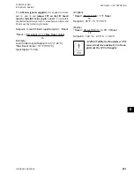
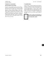
Assembly and Wiring
All components should be assembled and wired as
shown in Figure 61. Strip the outside insulation back
several inches and individual wires about 3/8" (9.5
mm) to connect the cable at the Microboard. Do not
connect the shield at the printer-end of the cable.
Obtaining a Printout
A printout is obtained by pressing the PRINT key on
the keypad and then pressing either the OPER DATA
key or HISTORY key.
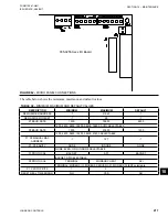
FIGURE 61 -
PRINTER TO MICROBOARD ELECTRICAL CONNECTIONS
LD12723
TB3-3 TXD
TB3-2 CTS
TB3-5 GND
TB3
2 RD
7 SG
5 CTS
Chiller Microboard
Printer
Do not connect shield
at printer end.
Shield (connect shield to Pin 5
of the connector.
Содержание YCAL0019
Страница 4: ...JOHNSON CONTROLS 4 FORM 150 67 NM1 ISSUE DATE 4 28 2017 THIS PAGE INTENTIONALLY LEFT BLANK...
Страница 14: ...JOHNSON CONTROLS 14 FORM 150 67 NM1 ISSUE DATE 4 28 2017 THIS PAGE INTENTIONALLY LEFT BLANK...
Страница 69: ...69 JOHNSON CONTROLS SECTION 5 TECHNICAL DATA FORM 150 67 NM1 ISSUE DATE 4 28 2017 5 5...
Страница 71: ...71 JOHNSON CONTROLS SECTION 5 TECHNICAL DATA FORM 150 67 NM1 ISSUE DATE 4 28 2017 5 5...
Страница 127: ...127 JOHNSON CONTROLS SECTION 5 TECHNICAL DATA FORM 150 67 NM1 ISSUE DATE 4 28 2017 5 5 DIMENSIONS YCAL0052 SI CONT D...
Страница 129: ...129 JOHNSON CONTROLS SECTION 5 TECHNICAL DATA FORM 150 67 NM1 ISSUE DATE 4 28 2017 5 5 DIMENSIONS YCAL0056 SI CONT D...
Страница 191: ...191 JOHNSON CONTROLS SECTION 8 UNIT OPERATION FORM 150 67 NM1 ISSUE DATE 4 28 2017 8 Figure 48 WIRING LD11799A...
Страница 202: ...JOHNSON CONTROLS 202 FORM 150 67 NM1 ISSUE DATE 4 28 2017 SECTION 8 UNIT OPERATION THIS PAGE INTENTIONALLY LEFT BLANK...
Страница 229: ...229 JOHNSON CONTROLS SECTION 10 MAINTENANCE FORM 150 67 NM1 ISSUE DATE 4 28 2017 NOTES...


