York G8C Series Скачать руководство пользователя страница 6

035-15241-003 Rev. A (201)

6

Unitary Products Group

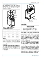
16. Install the top cap at the opposite end of furnace from the 

vent blower, using the seven sheet metal screws saved 
earlier. See Figure 3.

17. Install the bottom cap on the bottom of the furnace using 

the sheet metal screws saved earlier. See Figure 3.

18. The conversion is now complete. The furnace may now 

be installed in the downflow position or in the horizontal 
position on either side.

FURNACE LOCATION

This furnace is design certified for installation in an alcove,
closet, basement, attic, garage or utility room. The 50-125
MBH models may be installed in an upflow, downflow or hori-
zontal position on either side. The 150 MBH model may be
installed in an upflow or a horizontal left or right position. It is
certified only for use in a home constructed on-site or a man-
ufactured home completed at the final site. This furnace is not
design certified to be installed outdoors, in a mobile home,
trailer or recreational vehicle.

The furnace should be located as close to the chimney or
vent as possible and as close to the center of the warm air
distribution system as possible.

When the furnace is installed in a residential garage it must
be located and installed such that it will be protected from
damage by vehicles. The furnace must be installed so that
the burners are a minimum of 18" above the floor.

CLEARANES TO COMBUSTIBLE MATERIALS

Proper clearances from the furnace to any combustible mate-
rials must be maintained. These required minimum clear-
ances are shown below and on a label in the furnace.

Minimum Clearances - Upflow

Front:. . . . . . . . . . . . . . . . . 2 inches
Back: . . . . . . . . . . . . . . . . . 0 inches
Sides:  . . . . . . . . . . . . . . . . 0 inches
Top: . . . . . . . . . . . . . . . . . . 1 inch
B-1 Vent: . . . . . . . . . . . . . . 1 inch
Single-wall Vent: . . . . . . . . 6 inches
Floor  . . . . . . . . . . . . . . . . . combustible:

Minimum Clearances - Downflow

Front:  . . . . . . . . . . . . . . . . 2 inches
Back:. . . . . . . . . . . . . . . . . 0 inches
Sides: . . . . . . . . . . . . . . . . 0 inches
Top:. . . . . . . . . . . . . . . . . . 1 inch
B-1 Vent: . . . . . . . . . . . . . . 1 inch
Single-wall Vent: . . . . . . . . 6 inches
Floor:  . . . . . . . . . . . . . . . . non-combustible

For installation on combustible flooring only when installed on
the special downflow sub-base listed in the Specifications
Table on Page 3.

Minimum Clearances - Horizontal

Front:  . . . . . . . . . . . . . . . . 2 inches
Back:. . . . . . . . . . . . . . . . . 0 inches
Ends:  . . . . . . . . . . . . . . . . 1 inch
Top:. . . . . . . . . . . . . . . . . . 1 inch
B-1 Vent: . . . . . . . . . . . . . . 1 inch
Single-wall Vent: . . . . . . . . 6 inches
Floor:  . . . . . . . . . . . . . . . . combustible

When the furnace is installed in the horizontal position, line
contact is permissible. The line formed by the intersection of
the top and sides of the furnace may be in contact with com-
bustible material. 

Provide sufficient space around and in front of the furnace for
service and cleaning. Allow a minimum of 24 inches from the
front of the furnace for service clearance. If the furnace is to
be installed in a close clearance closet, the door should be of
adequate size to allow for removal of the furnace should it
become necessary.

.

NOTE:  

This furnace must be installed so the electrical com-

ponents are protected from water.
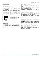
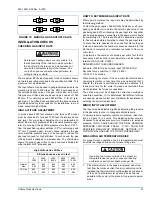
 FIGURE 5 : 

TOP CAP

UPFLOW

VENT

OPENING

DOWNFLOW

VENT

OPENING

Do not install the furnace on its back. Doing so
could cause a fire, resulting in damage, injury or
death.

Failure to maintain proper clearances to combus-
tible materials can cause a fire, which could result
in damage, death or personal injury.

Содержание G8C Series

Страница 1: ...OSITION 50 125 MBH Models 4 INSTALLATION POSITION 150 MBH Models 4 CONVERSION INFORMATION 50 125 MBH Models 4 TO CONVERT FROM DOWNFLOW TO UPFLOW CONFIGURATION 50 125 MBH Models 4 TO CONVERT FROM UPFLO...

Страница 2: ...aning compounds plastic items or con tainers gasoline kerosene cigarette lighter fluid dry cleaning fluids or other volatile fluid 3 Paint thinners and other painting com pounds 4 Paper bags boxes or...

Страница 3: ...000 60 000 1200 17 1 2 10 x 8 35 65 165 1 3 4 1FB0318 75 000 60 000 1600 21 10 x 10 30 60 160 1 2 4 1FB0319 100 000 80 000 1600 21 10 x 10 40 70 170 1 2 4 1FB0319 100 000 80 000 2000 24 1 2 2 10 x 6...

Страница 4: ...conversion instructions starting on Page 5 and Page 6 INSTALLATION POSITION 150 MBH Models This furnace may be installed in an upflow or horizontal poi sion No conversion is necessary CONVERSION INFO...

Страница 5: ...ion on the vent blower using the three screws supplied on the vent blower See Figure 4 10 Rotate the vent blower 180 so that its outlet points toward the inlet air end of the furnace See Figure 3 11 L...

Страница 6: ...to any combustible mate rials must be maintained These required minimum clear ances are shown below and on a label in the furnace Minimum Clearances Upflow Front 2 inches Back 0 inches Sides 0 inches...

Страница 7: ...the furnace If all air is from inside building the total free area of each opening must be at least one square inch for each 1 000 BTUH of furnace input but not less than 100 square inches If all air...

Страница 8: ...ply air duct attached to the furnace be provided with a removable access panel The opening should be accessible when the furnace is installed in service and should be large enough that smoke or reflec...

Страница 9: ...uired depending on the capacity of the air conditioner and the air flow required The return air opening in the top of the furnace is large enough for the largest capacity air conditioner for which the...

Страница 10: ...ecifics It is recommended that a gas cock shutoff valve be installed in the gas supply line outside the casing where it is readily accessible as close to the furnace as is practicable as shown in Figu...

Страница 11: ...ALVE PRESSURE SWITCH VENT VENT PIPE TRANSITION GAS PIPE 3 DIAMETER VENT PIPE GAS SHUT OFF VALVE ROLL OUT SWITCH DIRT LEG VENT BLOWER FURNACE CONTROL FIGURE 10 UPFLOW CONFIGURATION 50 125 MBH MODELS ON...

Страница 12: ...n the limits shown FIGURE 11 UPFLOW HORIZONTAL 150 MBH MODEL ONLY BLOWER DOOR SWITCH ROLL OUT SWITCHES BURNERS HOT SURFACE IGNITOR GAS VALVE PRESSURE SWITCH GAS PIPE GAS SHUT OFF VALVE ROLL OUT SWITCH...

Страница 13: ...nd fastened to the furnace flue collar using screws where required 9 Joints in the vent pipe must be securely made and any horizontal run of the vent pipe must be supported less than one support every...

Страница 14: ...rtical portion of the chimney or vent above the connector A vent connector must not pass through any ceiling floor firewall or fire partition A single wall metal pipe vent connec tor must not pass thr...

Страница 15: ...a device that keeps the power venter in operation for a short period at the end of each burner cycle in order to clear out all flue gases from the vent Manufacturers of power ven ters also can supply...

Страница 16: ...he furnace The furnace control board has a ter minal marked TWIN which can be used to cause two furnace blowers to operate together If two furnaces are to be twinned using a single wall thermo stat co...

Страница 17: ...TAP EXTERNAL STATIC PRESSURE INCHES W C 0 10 0 20 0 30 0 40 0 50 0 60 0 70 0 80 50 40 1200 75 60 1200 HIGH 1407 1367 1315 1279 1211 1138 1053 961 MED 1141 1130 1092 1059 1009 945 876 782 LOW 885 894 8...

Страница 18: ...r shorted wires bad pressure switch Three flashes Pressure switch failed to close Check vent blower pressure switch vent blockage disconnected pres sure hose Four flashes Limit switch open Check for o...

Страница 19: ...mally open pressure switch contacts 3 As the vent blower increases in speed the contacts of the pressure switch will close and complete the electrical circuit to the ignitor 4 During the next 30 secon...

Страница 20: ...not reach your gas supplier call the fire department 3 USE ONLY YOUR HAND TO MOVE THE GAS CON TROL LEVER OR SWITCH NEVER USE TOOLS IF THE LEVER OR SWITCH WILL NOT MOVE BY HAND DON T TRY TO REPAIR IT...

Страница 21: ...t is necessary to achieve the correct input rate use the following formula GAS VALUE X 3600 DESIRED INPUT SECONDS NEEDED Example 1000 BTU gas furnace input 100 000 BTUH Seconds for one cubic foot 1000...

Страница 22: ...g of the heat exchanger and flue gas pas sageways is not necessary and is not recommended under normal circumstances REPLACEMENT PARTS Should it be necessary to replace any component parts these may b...

Страница 23: ...Ignitor Bracket 15 Gas Orifice 16 Door Switch 17 Capacitor 18 Blower Wheel 19 Blower Motor 20 Sensor Rod 21 Blower Motor Clamp 22 Rubber Motor Mounts 23 Transition 24 Rollout Switch Bracket 25 Door La...

Страница 24: ...hout notice Printed in U S A 035 15241 003 Rev A 201 Copyright by York International Corp 2001 All rights reserved Supersedes 035 15241 002 Rev A 800 Unitary 5005 Norman Products York OK Group Drive 7...

Отзывы: