York G8C Series Скачать руководство пользователя страница 22

035-15241-003 Rev. A (201)

22

Unitary Products Group

2.

Place thermometer in return air duct about two feet from 
furnace, with the tip of the thermometer as near as possi-
ble to the center of the duct.

3.

Set thermostat to highest temperature setting and allow 
furnace to run for at least five minutes before checking 
temperatures.

4.

Calculate air temperature rise by subtracting supply air 
temperature from the return air temperature.

5.

If temperature rise is not within the range shown on the 
furnace rating plate, the blower speed may need to be 
changed.

6.

If the blower speed is changed, recheck the temperature 
rise by repeating steps 1 through 4 above.

7.

If the air temperature rise is not within the proper range 
even after changing blower speeds, check ductwork 
design with a qualified heating engineer. It may be nec-
essary to re-size the ductwork.

BALANCE THE SYSTEM

The air distribution system should be balanced, using in-line
duct dampers if employed, to provide for satisfactory air deliv-
ery to room. It is recommended that dampers in registers not
be used for balancing the system.

SERVICE INSTRUCTIONS

MOTOR LUBRICATION

The circulating air blower motor and vent blower are perma-
nently lubricated and do not require periodic lubrication.

BURNER CLEANING

The burners used in this furnace are specially designed to be
non-linting and should not require periodic cleaning. In the
event that cleaning does become necessary, use the suction
hose of a suitable vacuum cleaner to remove dirt and lint. Be
careful not to damage the ignitor or sensor rod during clean-
ing.

FLUE GAS PASSAGEWAYS

Periodic cleaning of the heat exchanger and flue gas pas-
sageways is not necessary and is not recommended under
normal circumstances.

REPLACEMENT PARTS

Should it be necessary to replace any component parts,
these may be obtained through an authorized dealer, who is
experienced and can be of assistance. Information on the
nearest Distributor may be obtained directly from the com-
pany shown on the furnace rating plate.

Following major service or replacement of functional parts, it
is recommended that the furnace be operated in the various
modes to insure that performance is normal and control com-
ponents are functioning properly.

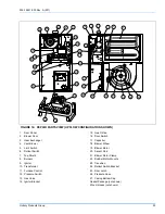
The parts listed below are only those that are functional parts
and those that might require replacement. The parts listed
are by part name (description) only and CODE reference
NUMBER. The CODE number is used to determine the loca-
tion of the part in the generalized, pictorial illustration pro-
vided. See Figure 16.

When ordering parts - order by name and description. Do not
order by code number. Also when ordering parts please pro-
vide:

1.

Complete furnace Model Number and Serial Number. 
These may be found on the rating plate located behind 
the front panel (door) of the furnace.

2.

Type of gas being used.

3.

Is furnace being used in conjunction with air conditioning 
or heat pump?

Never attempt to modify this furnace - fire, explo-
sion, or asphyxiation may result. If malfunction is
apparent, contact a qualified service agency and/
or gas utility for assistance.

Label all wires prior to disconnection when ser-
vicing controls. Wiring errors can cause improper
and dangerous operation.

Verify proper operation after servicing.

Only genuine

 Source One

 authorized replace-

ment parts should be used. Substitute parts
should not be used, as they may not be the same
in operational and safety characteristics.

Содержание G8C Series

Страница 1: ...OSITION 50 125 MBH Models 4 INSTALLATION POSITION 150 MBH Models 4 CONVERSION INFORMATION 50 125 MBH Models 4 TO CONVERT FROM DOWNFLOW TO UPFLOW CONFIGURATION 50 125 MBH Models 4 TO CONVERT FROM UPFLO...

Страница 2: ...aning compounds plastic items or con tainers gasoline kerosene cigarette lighter fluid dry cleaning fluids or other volatile fluid 3 Paint thinners and other painting com pounds 4 Paper bags boxes or...

Страница 3: ...000 60 000 1200 17 1 2 10 x 8 35 65 165 1 3 4 1FB0318 75 000 60 000 1600 21 10 x 10 30 60 160 1 2 4 1FB0319 100 000 80 000 1600 21 10 x 10 40 70 170 1 2 4 1FB0319 100 000 80 000 2000 24 1 2 2 10 x 6...

Страница 4: ...conversion instructions starting on Page 5 and Page 6 INSTALLATION POSITION 150 MBH Models This furnace may be installed in an upflow or horizontal poi sion No conversion is necessary CONVERSION INFO...

Страница 5: ...ion on the vent blower using the three screws supplied on the vent blower See Figure 4 10 Rotate the vent blower 180 so that its outlet points toward the inlet air end of the furnace See Figure 3 11 L...

Страница 6: ...to any combustible mate rials must be maintained These required minimum clear ances are shown below and on a label in the furnace Minimum Clearances Upflow Front 2 inches Back 0 inches Sides 0 inches...

Страница 7: ...the furnace If all air is from inside building the total free area of each opening must be at least one square inch for each 1 000 BTUH of furnace input but not less than 100 square inches If all air...

Страница 8: ...ply air duct attached to the furnace be provided with a removable access panel The opening should be accessible when the furnace is installed in service and should be large enough that smoke or reflec...

Страница 9: ...uired depending on the capacity of the air conditioner and the air flow required The return air opening in the top of the furnace is large enough for the largest capacity air conditioner for which the...

Страница 10: ...ecifics It is recommended that a gas cock shutoff valve be installed in the gas supply line outside the casing where it is readily accessible as close to the furnace as is practicable as shown in Figu...

Страница 11: ...ALVE PRESSURE SWITCH VENT VENT PIPE TRANSITION GAS PIPE 3 DIAMETER VENT PIPE GAS SHUT OFF VALVE ROLL OUT SWITCH DIRT LEG VENT BLOWER FURNACE CONTROL FIGURE 10 UPFLOW CONFIGURATION 50 125 MBH MODELS ON...

Страница 12: ...n the limits shown FIGURE 11 UPFLOW HORIZONTAL 150 MBH MODEL ONLY BLOWER DOOR SWITCH ROLL OUT SWITCHES BURNERS HOT SURFACE IGNITOR GAS VALVE PRESSURE SWITCH GAS PIPE GAS SHUT OFF VALVE ROLL OUT SWITCH...

Страница 13: ...nd fastened to the furnace flue collar using screws where required 9 Joints in the vent pipe must be securely made and any horizontal run of the vent pipe must be supported less than one support every...

Страница 14: ...rtical portion of the chimney or vent above the connector A vent connector must not pass through any ceiling floor firewall or fire partition A single wall metal pipe vent connec tor must not pass thr...

Страница 15: ...a device that keeps the power venter in operation for a short period at the end of each burner cycle in order to clear out all flue gases from the vent Manufacturers of power ven ters also can supply...

Страница 16: ...he furnace The furnace control board has a ter minal marked TWIN which can be used to cause two furnace blowers to operate together If two furnaces are to be twinned using a single wall thermo stat co...

Страница 17: ...TAP EXTERNAL STATIC PRESSURE INCHES W C 0 10 0 20 0 30 0 40 0 50 0 60 0 70 0 80 50 40 1200 75 60 1200 HIGH 1407 1367 1315 1279 1211 1138 1053 961 MED 1141 1130 1092 1059 1009 945 876 782 LOW 885 894 8...

Страница 18: ...r shorted wires bad pressure switch Three flashes Pressure switch failed to close Check vent blower pressure switch vent blockage disconnected pres sure hose Four flashes Limit switch open Check for o...

Страница 19: ...mally open pressure switch contacts 3 As the vent blower increases in speed the contacts of the pressure switch will close and complete the electrical circuit to the ignitor 4 During the next 30 secon...

Страница 20: ...not reach your gas supplier call the fire department 3 USE ONLY YOUR HAND TO MOVE THE GAS CON TROL LEVER OR SWITCH NEVER USE TOOLS IF THE LEVER OR SWITCH WILL NOT MOVE BY HAND DON T TRY TO REPAIR IT...

Страница 21: ...t is necessary to achieve the correct input rate use the following formula GAS VALUE X 3600 DESIRED INPUT SECONDS NEEDED Example 1000 BTU gas furnace input 100 000 BTUH Seconds for one cubic foot 1000...

Страница 22: ...g of the heat exchanger and flue gas pas sageways is not necessary and is not recommended under normal circumstances REPLACEMENT PARTS Should it be necessary to replace any component parts these may b...

Страница 23: ...Ignitor Bracket 15 Gas Orifice 16 Door Switch 17 Capacitor 18 Blower Wheel 19 Blower Motor 20 Sensor Rod 21 Blower Motor Clamp 22 Rubber Motor Mounts 23 Transition 24 Rollout Switch Bracket 25 Door La...

Страница 24: ...hout notice Printed in U S A 035 15241 003 Rev A 201 Copyright by York International Corp 2001 All rights reserved Supersedes 035 15241 002 Rev A 800 Unitary 5005 Norman Products York OK Group Drive 7...

Отзывы: