


035-15241-003 Rev. A (201)
Unitary Products Group
5
.
TO CONVERT FROM UPFLOW TO
DOWNFLOW CONFIGURATION
(50-125 MBH Models)
1.
Lay the furnace on its back.
2.
Remove the front door.
3.
Remove the seven sheet metal screws that are used to
fasten the top cap to the casing.
4.
Remove the four sheet metal screws that are used to
fasten the bottom cap to the casing. Remove the bottom
cap and save the screws.
5.
Unplug the vent blower wires.
6.
Disconnect the pressure hose from the vent blower.
7.
Remove the four machine screws that fasten the vent
blower to the vent pan and save the screws. Leave the
gasket in place on the vent pan.
8.
Remove the two extra machine screws in the vent pan
front and save the screws.
9.
Install the cast aluminum transition on the vent blower,
using the three screws supplied on the vent blower. See
Figure 4.
10. Rotate the vent blower 180º so that its outlet points
toward the inlet air end of the furnace. See Figure 3.
11. Line up the vent blower mounting holes with the holes in
the vent pan and screw it into place. Use the same
machine screws that held the vent blower in place previ-
ously.
12. Install the two extra machine screws in the two open
holes in the front of the vent pan. See Figure 3.
13. Plug in the vent motor wires.
14. Plug the pressure hose into the vent blower.
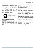
15. Remove the round knockout at the right side of the top
cap. See Figure 5.
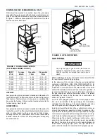
FIGURE 2 :
UPFLOW/HORIZONTAL
CONFIGURATION
FIGURE 3 :
DOWNFLOW/HORIZONTAL
CONFIGURATION
GASKET
EXTRA
SCREWS
TOP
CAP
TRANSITION
PRESSURE
HOSE
PRESSURE
SWITCH
VENT
BLOWER
BOTTOM
CAP
VENT
PAN
GASKET
EXTRA
SCREWS
TOP
CAP
TRANSITION
PRESSURE
HOSE
VENT
BLOWER
VENT
PAN
BOTTOM
CAP
FIGURE 4: VENT BLOWER
TRANSITION