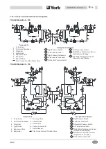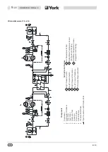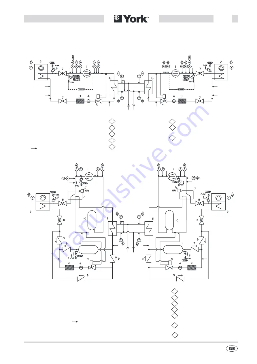
9.12 Process and Instrumentation Diagrams
(09/03)
035B09012-100 Rev. 4
9
-
21
1 Compressor
A
C
High Pressure Switch
High Pressure Transducer
2 Air Cooled Condenser
B
D
LowP ressure Switch
LowP ressure Transducer
3 Filter Drier
E Differential Pressure Switch
4 Sight Glass
F Air Temperature Sensor
5 Expansion Valve
G Outlet Water Temperature Sensor
6 Evaporator
(Antifreeze and Display)
7 Shut-off Valve
Pipe Connection with Shrader Valve
H Inlet Water Temperature Sensor
(Regulation and Display)
Safety/Control Devices
Components
YCAA-B Models 60 - 150
1 Compressor
A High Pressure Switch
2 Air Cooled Condenser
B LowP ressure Switch
3 Filter Drier
C
G
Differential Pressure Switch
Defrost Pressure Switch
4 Sight Glass
D Air Temperature Sensor
5 Expansion Valve
E Outlet Water Temperature Sensor
6 Evaporator
(Antifreeze and Display)
7 Four-way Valve
F Inlet Water Temperature Sensor
8 Shut-off Valve
(Regulation and Display)
9 Check Valve
10 Suction Accumulator
11 Liquid Receiver
Pipe Connection with Shrader Valve
Components
Safety/Control Devices
YCAA-H Models 60 - 150
Содержание YCAA B 120
Страница 2: ......
Страница 16: ...This Page Left Intentionally Blank 09 03 2 6 035B09012 100 Rev 4 ...
Страница 28: ...This Page Left Intentionally Blank 09 03 4 10 035B09012 100 Rev 4 ...
Страница 36: ...Page Left Intentionally Blank 09 03 6 6 035B09012 100 Rev 4 ...
Страница 40: ...Page Left Intentionally Blank 09 03 7 4 035B09012 100 Rev 4 ...
Страница 68: ...Notes 09 03 11 2 035B09012 100 Rev 4 ...
Страница 69: ...Notes 09 03 035B09012 100 Rev 4 11 3 ...
Страница 70: ...Notes 09 03 11 4 035B09012 100 Rev 4 ...

