4
INSTALLATION
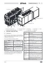
4.1
Location
Before installing the unit, make sure that
the building structure and/or mounting
surface can support the unit weight.
Overall weights and weight distribution
are detailed in Section 9.
The unit should not be installed directly on
flammable materials such as wooden
structures or roofs.
The unit has been designed for floor mounting in outside
locations. Rubber anti-vibration pads are supplied as
standard and they must be positioned centrally,
underneath each of the supporting plates.
When the unit is to be installed on the ground, a concrete
slab must be provided to ensure uniform weight
distribution.
Special mounts are not normally required. However, if
the unit is to be installed directly above inhabited rooms,
it is advisable to fix the unit on spring isolators (supplied
as accessories, refer to Section 9) to minimise the
vibrations transmitted to the structure.
The following factors must be considered when
selecting a location for the unit:
n
The units longitudinal axis should be parallel to
prevailing winds to ensure balanced air flow over
the condenser coils.
n
The unit should not be sited downwind of boiler
flues.
n
The unit should not be sited downwind of sources
of grease-laden air such as extractor vents for
large kitchens. In such cases, accumulated grease
on the condenser fins can trap airborne
contaminants, thus leading to rapid soiling or
clogging.
n
The unit should not be sited in areas exposed to
heavy snowfall.
n
The unit should not be sited in areas exposed to
flooding or beneath downpipes, etc.
n
The unit should not be sited in air wells, courtyards
or other restricted spaces where noise would be
reverberated off the walls, or where air expelled by
fans could be channeled back to condenser inlets.
n
The installation position should ensure adequate
clearances for air circulation and maintenance,
refer to Section 9 for details.
4.2
Defrost Water Drainage (YCAA-H Units)
When YCAA-H units operate in the heat pump mode,
water will drain from under the unit base during regular
defrost cycles.
The unit should be installed with a minimum ground
clearance of 200 mm to allow the defrost water to drain
freely without ice build-up below the unit.
Drip trays and drain pipes should not be installed under
the unit in areas where the outdoor temperature may
drop below freezing, as an ice build-up may occur.
YCAA-H units must be installed where the defrost water
will not damage surrounding areas.
4.3
Spring Isolator Installation
n
Prepare base ground, which should be smooth and
level.
n
Lift the unit and insert the mounts in accordance
with the Spring Isolator Installation instructions in
Section 9.
(09/03)
035B09012-100 Rev. 4
4
-
1
Содержание YCAA B 120
Страница 2: ......
Страница 16: ...This Page Left Intentionally Blank 09 03 2 6 035B09012 100 Rev 4 ...
Страница 28: ...This Page Left Intentionally Blank 09 03 4 10 035B09012 100 Rev 4 ...
Страница 36: ...Page Left Intentionally Blank 09 03 6 6 035B09012 100 Rev 4 ...
Страница 40: ...Page Left Intentionally Blank 09 03 7 4 035B09012 100 Rev 4 ...
Страница 68: ...Notes 09 03 11 2 035B09012 100 Rev 4 ...
Страница 69: ...Notes 09 03 035B09012 100 Rev 4 11 3 ...
Страница 70: ...Notes 09 03 11 4 035B09012 100 Rev 4 ...


