PAGE 4
MAXA-MI$ER
Ô
UNITARY ENERGY RECOVERY VENTILATOR
MODEL VR028A15M/H & VR028A25H (STATIONARY)
INSTALLATION
INSTRUCTIONS
5257527-UAI-A-0616 / R28A-18YSDW
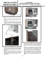
19. Secure the side flanges of the UERV to the holes in the
adaptor panels installed earlier using the provided
screws.
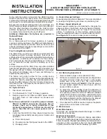
20. Check along the edges where the UERV meets the
adaptor panels and where the adapter panels meet
the RTU and seal where necessary. There should be
no air leakage and the final UERV assembly should be
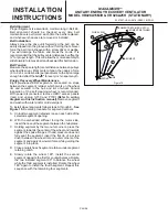
weather tight. Final assembly should resemble
Figure
12
.
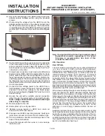
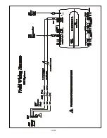
FUSE BLOCK
Figure 13
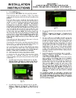
Note: If using this ERV with the York Simplicity Smart
Equipment products upgrading to the latest
firmware is recommended. See back of this
manual for instructions.
VIII - Op er a tion
How It Works
The unit contains an Energy Recovery Wheel (ERW) that
is a new concept in rotary air-to-air heat exchanger.
Designed as a packaged unit for ease of installation and
maintenance, only matching up to rooftop unit with an
internal balancing damper and connection of electrical
power is required to make the system operational. The
concept consists of a unique rotary energy recovery wheel
that rotates in and out of fresh air streams within a heavy
duty, permanently installed blower cabinet that provides
ready access to all internal components. The media is
polymeric material that is coated and permanently bonded
with a dry desiccant for total enthalpy recovery. The wheel
is belt driven by PSC motor and drive belt.
When slowly rotating through counter flowing exhaust and
fresh air streams the UERV adsorbs sensible heat and
latent heat from the warmer air stream and transfer this
total energy to the cooler air stream during the second half
of its rotating cycle. Rotating at 60 revolutions per minute,
the wheel provides constant flow of energy from warmer to
cooler air stream. The large energy transfer surface and
laminar flow through the wheel causes this constant flow
of recovered energy to represent up to 85% of the
difference in total energy contained within the two air
streams.
Sensible and latent heat are the two components of total
heat. Sensible heat is energy contained in dry air and latent
heat is the energy contained within the moisture of the air.
The latent heat load from the outdoor fresh air on an air
conditioning system can often be two to three times that of
the sensible heat load and in the winter it is a significant
part of a humidification heat load.
Figure 12
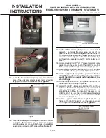
21. On the UERV open the access panel on the right side
of the name plate.Connect the wiring harness to the 3
prong connector located near the bottom of this
access panel on one end and the "ex-fan" and "com"
connectors on the other.
22. All electrical connections must meet current National
Electric Codes (NEC) and/or Canadian Electric Code
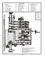
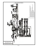
(CEC). Refer closely to the wiring diagram in unit or in
these instructions for proper connections. Refer to the
units Nameplate for the minimum circuit ampacity and
the Maximum Over Current protection size. Electrical
data is listed both on the nameplates and the individual
motor nameplates.
23. Connect the line voltage power to the UERV from a
field installed power disconnect through provided
knockout. Connect line voltage to the fused power
block per wiring diagram,
Figure 13
shows the control
box and wiring.
24. Ground the unit with a suitable ground connection
either through the supply wiring or and earth ground.
Units voltage entries must be sealed weather tight
after wiring is complete.
25. Restore power to the unit.
26. Start system up to verify operation.
27. Replace access panels on UERV and return air
section of the RTU and secure.
28. Cleanup once UERV is operating properly, caulk open
joints holes or seams to make the unit weather tight.
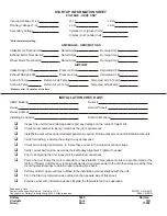
29. Fill out installation checklist and startup sheet in the
back of these instructions.
30. Leave this manual with the owner or in an envelope
inside the unit.
Содержание VR028A15H
Страница 9: ...PAGE 9 ...
Страница 12: ...PAGE 12 EQUIPMENT LAYOUT ...


