
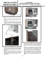


3.
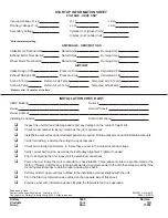
Remove the return duct cover from the floor of the
RTU.
4.
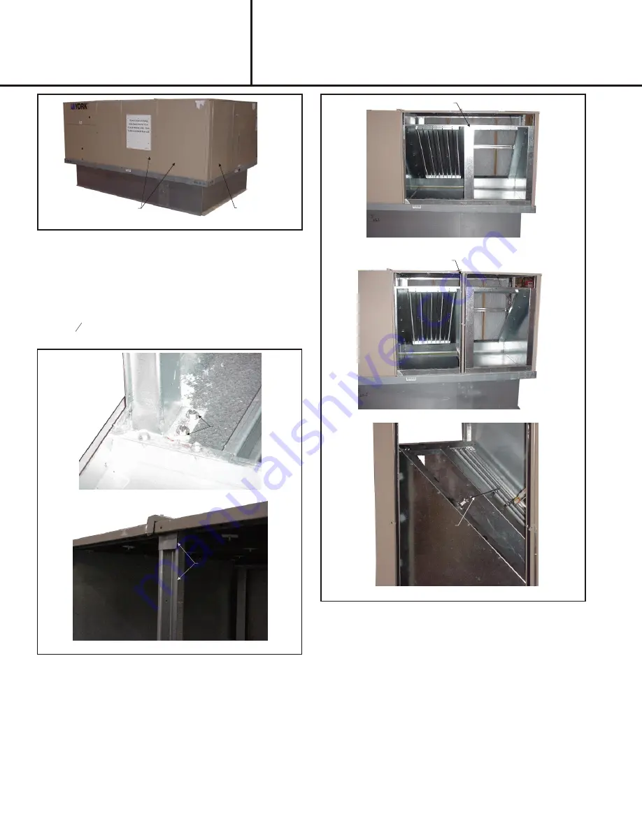
Remove the 9 screws holding the painted outside
center post between the horizontal return air
openings.
5.
Remove the galvanized inside center post by
removing the clip and two screws on the top, and the
two
3
8
" head screws on the bottom.
See Figures 2 and
3.
PAGE 2
MAXA-MI$ER
Ô
UNITARY ENERGY RECOVERY VENTILATOR
MODEL VR028A15M/H & VR028A25H (STATIONARY)
INSTALLATION
INSTRUCTIONS
5257527-UAI-A-0616 / R28A-18YSDW
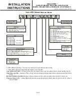
Figure 1
REMOVE
FILTER ACCESS
REMOVE
REMOVE
Figure 2
Figure 3
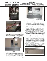
BALANCING DAMPER
Figure 4
REINSTALL CENTER POST
Figure 5
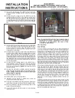
Figure 6
ADJUSTMENT
ROD
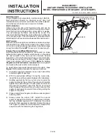
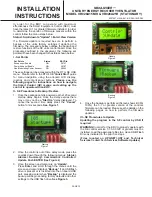
8.
Mount the SE-ECO1001 economizer control board in
the return air compartment on the balancing damper
frame within reach of field wiring harness.
See Figure
7.
9.
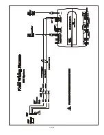
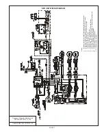
Connect the communication wire and power wire
located in the accessory wiring bundle in the RTU
return air section to the proper terminals on the
economizer control board (See SSE field harness
diagram at the back of this manual).
See Figure 8.
10. Route the provided field wiring harness through the
balancing damper into the return air section of the
rooftop unit, coil the excess wire inside the RTU in
order to keep it clear during the installation of the
UERV.
6.
Install the provided balancing damper assembly into
the return air section of the RTU as shown in
Figure 4
.
Reinstall the painted outside center post as shown in
Figure 5
.
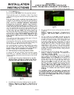
7.
Adjusting the balancing damper for the minimum
airflow requirements can be done by loosening the
wingnut on the quadrant and then moving the
quadrant handle to set the return dampers in place.
See Figure 6.
Содержание VR028A15H
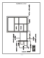
Страница 9: ...PAGE 9 ...
Страница 12: ...PAGE 12 EQUIPMENT LAYOUT ...


