


<4. Control Application Creation>
58
TI 34P02K35-02E Jun. 6, 2018-00
4.7 Handling Compile Errors and Warnings
When compiling a project in Logic Designer, compile errors and warnings may
sometimes be displayed as a compile result.
A compile error indicate the presence of a system error or a syntax error in the
application program that prevents successful completion of compile. Performing
downloading without first removing all compile errors will cause invalid code to be
downloaded, thus affecting normal control. To avoid this, always fix and remove all
compile errors before downloading.
On the other hand, compile warnings are not errors but may also affect normal
control if ignored. Fix all reported compile warnings.
TIP
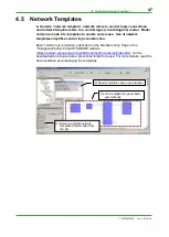
Performing downloading without first removing all compile errors will cause the following dialog to be
displayed.
Figure Compilation Error Message Dialog
● Compile Warning Example
Shown below is a list of warnings generated during compile of a project. The list of
warnings includes a warning which, if left unresolved, affects normal control.
Message displayed at the end of compile
0 Error(s), 34 Warning(s)
Detailed description of warnings
Worksheet empty.
Worksheet empty.
:
:
Variable 'NewVar4' is never used.
Variable 'NewVar3' is never used.
Variable 'NewVar2' is never used.
Variable 'NewVar1' is never used.
Variable 'ALARM_HI' is never used.
Instance 'SAMPLE_1' is never used.
Instance 'R_TRIG_1' is used more than once.
Variable 'V07' is never used.
Variable 'GM_ALRM_HI' is never used.
Variable 'V006' is never used.
Variable 'V007' is never used.
Содержание STARDOM FCN-500
Страница 2: ...Blank Page...
Страница 10: ...Blank Page...
Страница 32: ...Blank Page...
Страница 36: ...TI 34P02K35 02E Jun 6 2018 00 Blank Page...
Страница 76: ...TI 34P02K35 02E Jun 6 2018 00 Blank Page...
Страница 163: ...Blank Page...
Страница 221: ...Blank Page...
Страница 225: ...Blank Page...


