background image

IM 01E20F02-01E

6-2

6.  IN-PROCESS OPERATION

6.3 Simulation Function

The simulation function simulates the input of a
function block and lets it operate as if the data was
received from the transducer block. It is possible to
conduct testing for the downstream function blocks or
alarm processes.

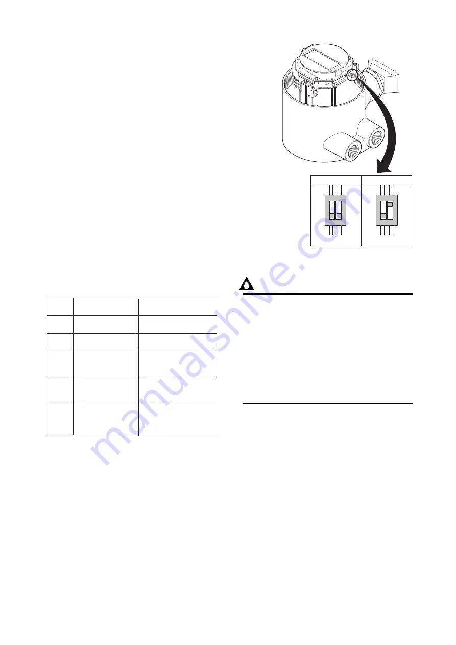
A SIMULATE_ENABLE switch is mounted in the
AXF amplifier. This is to prevent the accidental
operation of this function. When this is switched on,
simulation is enabled. (See Figure 6.2.) To initiate the
same action from a remote terminal, if REMOTE
LOOP TEST SWITCH is written to the
SIM_ENABLE_MSG parameter (index 1044) of the
resource block, the resulting action is the same as is
taken when the above switch is on. Note that this
parameter value is lost when the power is turned OFF.
In simulation enabled status, an alarm is generated
from the resource block, and other device alarms will
be masked; for this reason the simulation must be
disabled immediately after using this function.

The SIMULATE parameter of AI and DI block
consists of the elements listed in Table 6.2 below.

Table 6.2

Simulate Parameter (SIMULATE/SIMULATE_D)

T0602.EPS

Sub-

index

Parameters

Description

1

Simulate Status

Sets the data status to be 
simulated.

2

Simulate Value

Sets the value of the data 
to be simulated.

3

Transducer Status

Displays the data status 
from the transducer block.  
It cannot be changed.

4

Transducer Value

Displays the data value 
from the transducer block.  
It cannot be changed.

5

Enable Disable

Controls the simulation 
function of this block.
 1: Disable (standard)
 2: Active

When Simulate “Enable Disable” in Table 6.2 above is
set to 2, the applicable function block uses the simula-
tion value set in this parameter instead of the data from
the transducer block. This setting can be used for
propagation of the status to the trailing blocks, genera-
tion of a process alarm, and as an operation test for
trailing blocks.

2

1

O

N

2

1

O

N

Normal Operation Simulate Enable

SW101

SW101

F0602.eps

Figure 6.2 SIMULATE_ENABLE Switch Position

IMPORTANT

• Removing and installing cover are necessary

for the setting SIMULATE_ENABLE switch.
Perform removing and installing cover as
described in following Section of user’s manual.
Refer to Section 5.4.2.1 and Section 5.4.2.3 of
IM01E20D01-01E, or refer to Section 10.1.2.1
and Section 10.1.2.3 of IM01E20C02-01E.

• To preserve the safety, do not touch the

electrical circuit and cable except the
SIMULATE_ENABLE switch.

Содержание ADMAG AXF Series

Страница 1: ...Yokogawa Electric Corporation User s Manual IM01E20F02 01E ADMAG AXF Series FOUNDATION Fieldbus Communication Type Magnetic Flowmeter IM01E20F02 01E 3rd Edition ...

Страница 2: ... DD 3 3 3 5 Reading the Parameters 3 3 3 6 Continuous Record of Values 3 4 3 7 Generation of Alarm 3 4 4 CONFIGURATION 4 1 4 1 Network Design 4 1 4 2 Network Definition 4 1 4 3 Definition of Combining Function Blocks 4 2 4 4 Setting of Tags and Addresses 4 3 4 5 Communication Setting 4 4 4 5 1 VCR Setting 4 4 4 5 2 Function Block Execution Control 4 5 4 6 Block Setting 4 5 4 6 1 Link Object 4 5 4 ...

Страница 3: ...ducer Block 8 4 8 3 AI Function Block 8 9 8 4 Dl Function Block 8 11 9 GENERAL SPECIFICATIONS 9 1 9 1 STANDARD SPECIFICATIONS 9 1 9 2 OPTIONAL SPECIFICATIONS 9 2 9 3 TERMINAL CONNECTION 9 3 10 MAINTENANCE 10 1 APPENDIX 1 APPLICATION SETTING AND CHANGE OF BASIC PARAMETERS A 1 A1 1 Applications and Selection of Basic Parameters A 1 A1 2 Setting and Change of Basic Parameters A 2 A1 3 Setting the AI ...

Страница 4: ...rocess A 14 A2 7 List of Integrator Block Parameters A 15 APPENDIX 3 ARITHMETIC AR BLOCK A 17 A3 1 Schematic Diagram of Arithmetic Block A 17 A3 2 Input Section A 18 A3 2 1 Main Inputs A 18 A3 2 2 Auxiliary Inputs A 18 A3 2 3 INPUT_OPTS A 19 A3 2 4 Relationship between the Main Inputs and PV A 19 A3 3 Computation Section A 20 A3 3 1 Computing Equations A 20 A3 3 2 Compensated Values A 20 A3 3 3 Av...

Страница 5: ...ured value Tracking A 37 A5 14Initialization and Manual Fallback IMan A 38 A5 15Manual Fallback A 38 A5 16Auto Fallback A 38 A5 17Mode Shedding upon Computer Failure A 39 A5 17 1 SHED_OPT A 39 A5 18Alarms A 39 A5 18 1 Block Alarm BLOCK_ALM A 39 A5 18 2 Process Alarms A 39 A5 19Example of Block Connections A 40 A5 20View Object for PID Function Block A 40 APPENDIX 6 SOFTWARE DOWNLOAD A 42 A6 1 Bene...

Страница 6: ...to implied warranty of merchantability and fitness for a particular purpose If any question arises or errors are found or if any information is missing from this manual please inform the nearest Yokogawa sales office The specifications covered by this manual are limited to those for the standard type under the specified model number break down and do not cover custom made instruments Please note t...

Страница 7: ...ersonnel No operator shall be permitted to perform proce dures relating to wiring When connecting the wiring check that the supply voltage is within the range of the voltage specified for this instrument before connecting the power cable In addition check that no voltage is applied to the power cable before connecting the wiring The protective grounding must be connected securely at the terminal w...

Страница 8: ...ance with the design specifications Use of the product in question in a location not conforming to the standards specified by Yokogawa or due to improper maintenance of the installation location Failure or damage due to modification or repair by any party except Yokogawa or an approved representative of Yokogawa Malfunction or damage from improper relocation of the product in question after delive...

Страница 9: ...e flow sensor output to the volumetric flow rate signal and transfers to the AI function block Transfers limit switch signals to DI function blocks Adhesion diagnosis levels are set and monitored 3 AI function blocks Condition raw data from the transducer block including scaling and damping with a first order lag and allow input simulation Outputs volumetric or mass flow rate signals 4 DI function...

Страница 10: ...stem Configuration The number of devices that can be connected to a single bus and the cable length vary depending on system design When constructing systems both the basic and overall design must be carefully considered to achieve optimal performance ...

Страница 11: ...he instruction manual for each host No other details on the host are given in this manual Cable Used for connecting devices Refer to Fieldbus Technical Information TI 38K03A01 01E for details of instrumentation cabling For laboratory or other experimental use a twisted pair cable two to three meters in length with a cross section of 0 9 mm2 or more and a cycle period of within 5 cm 2 inches may be...

Страница 12: ...ime is in octets 256 µs Set maximum specification for all devices For AXF set a value of 4 or greater Slot Time V ST First Unpolled Node Minimum Inter PDU Delay Maximum Reply Delay Unused address range Indicate the address next to the address range used by the host Set 0 15 or greater Number of consecutive Unpolled Node The worst case time elapsed until a reply is recorded The unit is Slot time se...

Страница 13: ... set a different address for each 3 4 Integration of DD If the host supports DD Device Description the DD of the AXF needs to be installed Check if host has the following directory under its default DD directory 594543 000B 594543 is the manufacturer number of Yokogawa Electric Corporation and 000B is the AXF device number respectively If this directory is not found the DD of the AXF has not been ...

Страница 14: ...cessary to set the schedule of Publish the function that transmits the indication on a periodic basis 3 7 Generation of Alarm Generation of an alarm can be attempted from AXF Block alarm Output limit alarm and Update alarm are informed to the host When generating alarm a Link Object and a VCR Static Entry need to be set For details of Link Object and VCR Static Entry refer to section 4 6 1 Link ob...

Страница 15: ...terminators that are attached to the host Field devices Connect the field devices necessary for instrumenta tion The AXF has passed the interoperability test conducted by The Fieldbus Foundation In order to properly start Fieldbus it is recommended that the devices used satisfy the requirements of the above test Host Used for accessing field devices A minimum of one device with the bus control fun...

Страница 16: ... Set to LM Devices Indicates the time necessary for immediate reply of the device Unit of time is in octets 256 µs Set maximum specification for all devices For AXF set a value of 4 or greater T0402 EPS Symbol Parameters Description and Settings V ST Slot Time V MID Minimum Inter PDU Delay Minimum value of communication data intervals Unit of time is in octets 256 µs Set the maximum specification ...

Страница 17: ...and Addresses This section describes the steps in the procedure to set PD Tags and node addresses in the AXF There are three states of Fieldbus devices as shown in Figure 4 4 and if the state is other than the lowest SM_OPERATIONAL state no function block is executed AXF must be transferred to this state when an AXF tag or address is changed UNINITIALIZED No tag nor address is set Tag clear Tag se...

Страница 18: ...parameters may cause inconsistent operation Table 4 4 VCR Static Entry T0404 1 EPS Sub index Parameter Description 1 FasArTypeAndRole Indicates the type and role of communication VCR The following 4 types are used for AXF 0x32 Server Responds to requests from host 0x44 Source Transmits alarm or trend 0x66 Publisher Sends AI block output to other blocks 0x76 Subscriber Receives output of other bloc...

Страница 19: ...nd schedule of execution 4 6 Block Setting Set the parameter for function block VFD 4 6 1 Link Object A link object combines the data voluntarily sent by the function block with the VCR The AXF has 40 link objects A single link object specifies one combination Each link object has the parameters listed in Table 4 6 Parameters must be changed together for each VCR because the modifications made to ...

Страница 20: ...nalog mode parameters and one is used for Trend in discrete mode parameter A single Trend object specifies the trend of one parameter Each Trend object has the parameters listed in Table 4 8 The first four parameters are the items to be set Before writing to a Trend object it is necessary to release the WRITE_LOCK parameter Table 4 8 Parameters for Trend Objects T0408 EPS Sub index Parameters Desc...

Страница 21: ...26 SHED_RCAS 27 SHED_ROUT 1 28 FAULT_STATE 29 SET_FSAFE 30 CLR_FSAFE 2 2 2 4 4 4 4 4 1 2 1 1 2 2 1 4 2 byte T0411 2 EPS 22 30 73 35 4 4 4 4 4 4 4 1 1 2 1 16 2 46 DEVICE_STATUS_2 47 DEVICE_STATUS_3 48 DEVICE_STATUS_4 49 DEVICE_STATUS_5 50 DEVICE_STATUS_6 51 DEVICE_STATUS_7 52 53 54 55 56 57 58 DEVICE_STATUS_8 Totals SOFTDWN_PROTECT SOFTDWN_ERROR SOFTDWN_MOD_REV SOFTDWN_ACT_AREA SOFTDWN_COUNT SOFTDW...

Страница 22: ... 1 4 4 4 4 4 1 1 4 1 1 2 4 2 2 1 5 5 2 2 2 1 2 11 4 2 2 11 32 1 2 2 1 32 7 32 2 2 2 2 2 VELOCITY_CHECK DENSITY_UNIT MASS_FLOW_DENSITY LIMSW_1_VALUE_D LIMSW_1_TARGET LIMSW_1_SETPOINT LIMSW_1_ACT_DIRECTION LIMSW_1_HYSTERESIS LIMSW_1_UNIT LIMSW_2_VALUE_D LIMSW_2_TARGET LIMSW_2_SETPOINT LIMSW_2_ACT_DIRECTION LIMSW_2_HYSTERESIS LIMSW_2_UNIT SWITCH_1_VALUE_D SWITCH_1_TARGET SWITCH_2_VALUE_D SWITCH_2_TAR...

Страница 23: ..._LIM 33 HI_HI_ALM 34 HI_ALM 35 LO_ALM 36 LO_LO_ALM 2 11 11 2 2 4 2 5 5 5 5 8 2 2 1 31 26 31 46 2 2 2 1 4 4 2 4 1 4 1 4 1 4 1 4 VIEW _1 VIEW _2 VIEW _3 VIEW _4 Relative Index Parameter Total Table 4 14 View Object for DI DI1 DI2 Function Block byte T0414 EPS 1 ST_REV 2 2 TAG_DESC 3 STRATEGY 4 ALERT_KEY 5 MODE_BLK 4 6 BLOCK_ERR 2 7 PV_D 8 OUT_D 2 9 SIMULATE_D 10 XD_STATE 11 OUT_STATE 12 GRANT_DENY 1...

Страница 24: ...35 1 36 2 11 2 1 1 2 4 4 2 4 5 5 5 2 2 2 2 2 4 4 4 4 4 4 1 2 2 1 52 17 64 42 2 4 4 4 1 2 4 4 4 4 37 4 2 38 2 39 40 41 4 VIEW _1 VIEW _2 VIEW _3 VIEW _4 Relative Index Parameter Total Table 4 16 View Object for AR Function Block byte 2 5 4 T0417 EPS 1 ST_REV TAG_DESC STRATEGY ALERT_KEY MODE_BLK BLOCK_ERR PV OUT PRE_OUT PV_SCALE OUT_RANGE GRANT_DENY INPUT_OPTS IN IN_LO IN_1 IN_2 IN_3 RANGE_HI RANGE_...

Страница 25: ...1751 41750 40613 40203 40403 40603 PID Function Block IT1 Function Block IT2 Function Block AR Function Block DI2 Function Block AI Function Block DI1 Function Block Transducer Block 40102 40101 40100 40103 Resourse Block 4 6 4 Function Block Parameters Function block parameters can be read from the host or can be set For a list of the parameters of Resource block Transducer block AI block and DI ...

Страница 26: ... has relatively simple functions 5 2 Setting and Changing Param eters for the Whole Process IMPORTANT Do not turn off the power immediately after setting When the parameters are saved to the EEPROM the redundant processing is executed for an improvement of reliability If the power is turned off within 60 seconds after setting is made the modified parameters are not saved and the setting may return...

Страница 27: ...te operation Dual freq operation Rate limit damping Lowcut Limit check Adhesion check F0501 eps Historical records PRIMARY_VALUE Channel1 LIMSW_1_VALUE_D Channel2 LIMSW_2_VALUE_D Channel3 SWITCH_1_VALUE_D Channel4 SWITCH_2_VALUE_D Channel5 Figure 5 3 1 Diagram of the Transducer Block For a list of the parameters of each block of the ADMAG AXF refer to List of parameters for each block of the ADMAG...

Страница 28: ...ss flow 101 volumetric flow 102 average mass flow 103 average volumetric flow 65535 other Factory default is 101 volumetric flow ALARM_PERFORM 1 Overview This parameter masks Alarm Warning By setting 0 to each bit corresponding Alarm Warning are cleared When masked the corresponding bit of DEVICE_STATUS becomes OFF and no alarm is displayed on LCD and also becomes out of scope of Primary value sta...

Страница 29: ...list of the parameters of blocks held by the ADMAG AXF refer to List of parameters for each block of the ADMAG AXF in Chapter 8 The following is a list of important parameters with a guide how to set them TAG_DESC MODE_BLK Indicates the three types of function block modes Out_Of_Service Manual and Auto TAG_DESC indicates what mode of operation is desired for AI Function block In Out_Of_Service O S...

Страница 30: ...nt 0 Not Limited 1 Low Limited 2 High Limited 3 Constant Critical Alarm is Active Uncertain Engineering Unit Range Violation Out of sensor operating range Out of range of min span and max span No specific FB board EEPROM failure TB is O S BLOCK_ERR is O S etc Device Failure EEPROM failure Internal communication error Sensor Failure CPU board failure Bad Out of Service RS AI are O S T0503 eps XD_SC...

Страница 31: ...S Oil h 1487 kbbl US Oil min 1485 bbl US Oil min 1372 mbbl US Oil min 1484 bbl US Oil min 1483 kbbl US Oil s 1481 bbl US Oil s 1371 mbbl US Oil s 1480 bbl US Oil s 1479 kbbl US Beer d 65525 bbl US Beer d 65529 mbbl US Beer d 65533 kbbl US Beer h 65524 bbl US Beer h 65528 mbbl US Beer h 65532 bbl US Beer min 65527 mbbl US Beer min 65531 bbl US Beer min 65535 bbl US Beer s 65526 mbbl US Beer s 65530...

Страница 32: ...al mode does not allow values to be updated The Auto mode permits the measured value to be updated Under normal circum stances set the Auto mode to take effect The Auto mode is the factory default CHANNEL This is the parameter to specify the value of the transducer block to be input to the DI block Value Content 2 LIMSW_1 3 LIMSW_2 4 SWITCH_1 5 SWITCH_2 T0505 eps Each DI block is assigned to eithe...

Страница 33: ...ace Flow Rate Flow rate is displayed together with the units set in XD_SCALE the maximum number of figures is six 1 2 3 4 5 6 k g a l i n m F R F0506 eps In the case of L_TYPE is Direct decimal point location of the data becomes as follows XD_SCALE Decimal_Point XD_SCALE Decimal_Point Desimal Desimal Point Point Location Location Example Example 0 0 123 1 1 123 4 2 2 3 123 45 3 123 456 Other Auto ...

Страница 34: ...l US Oil h mbbl h 1484 mbbl US Oil min mbbl min 1480 mbbl US Oil s mbbl s 1491 ubbl US Oil d 1487 ubbl US Oil h 1479 ubbl US Oil s bbl s 65525 kbbl US Beer d kbbl d 65524 kbbl US Beer h kbbl h 65529 bbl US Beer d bbl d 65528 bbl US Beer h bbl h 65527 bbl US Beer min bbl min 65526 bbl US Beer s bbl s 65533 mbbl US Beer d mbbl d 65532 mbbl US Beer h mbbl h 65531 mbbl US Beer min mbbl min 65530 mbbl ...

Страница 35: ... e F R A D H v e l 4 F0513 eps Level3 Adhesion Level4 Adh Measure Value Adhesion Level3 1 2 3 4 5 l h 6 L e F R A D H v e l 3 F0514 eps Level2 Adhesion Level3 Adh Measure Value Adhesion Level2 1 2 3 4 5 l h 6 L e F R A D H v e l 2 F0515 eps Level1 Adhesion Level2 Adh Measure Value Adhesion Level1 1 2 3 4 5 l h 6 L e F R A D H v e l 1 F0516 eps Level0 Adhesion Level1 Adh Measure Value 1 2 3 4 5 l h...

Страница 36: ...6 M l 1 I T 2 F R C O M d a t i o n F o u n d b u s F i e l s c P r o e s r m a A l p 3 1 E m i p e P t y l l F i l f w u b e t o w i t h i f l u d 1 0 0 1 2 l h 3 2 3 4 5 6 M l 1 I T 2 F R C O M d a t i o n F o u n d b u s F i e l Alarm generated Data is fixed at the value when alarm generated F0519 eps Alarm Message Countermeasure Message On the Integral LCD indicator following messages are disp...

Страница 37: ...mode Span flow velocity setting is 11 m s or more Span flow velocity setting is 0 05 m s or less Mass units have been selected for Base Flow Unit but density is set to zero Measure Mode is set to Enhanced DF without selecting an optional code HF1 or HF2 A value of 3000 1 mm or more is set for Nominal Size The condition in Adhesion detection level Level 1 Level 2 Level 3 Level 4 is not satisfied IT...

Страница 38: ... 155 AR FB Man Mode 156 PID FB Man Mode 160 PID FB Bypass Mode Slight adhesion to electrodes Results of automatic zero adjustment are higher than the rated value Overflow in the display digits during instantaneous flow rate display PRIMARY_VALUE exceeds 108 of Span AI Block not scheduled IT1 Block not scheduled IT2 Block not scheduled DI1 Block not scheduled DI2 Block not scheduled AR Block not sc...

Страница 39: ...termeasure message Description of warning F0601 EPS Figure 6 1 Error Identification on Indicator 6 2 2 Alarms and Events The following alarms or events can be reported by the AXF if Link object and VCR static entry are set Analog Alerts Generated when a process value exceeds threshold By AI Block Hi Hi Alarm Hi Alarm Low Alarm Low Low Alarm Discrete Alerts Generated when an abnormal condition is d...

Страница 40: ...ATE_D T0602 EPS Sub index Parameters Description 1 Simulate Status Sets the data status to be simulated 2 Simulate Value Sets the value of the data to be simulated 3 Transducer Status Displays the data status from the transducer block It cannot be changed 4 Transducer Value Displays the data value from the transducer block It cannot be changed 5 Enable Disable Controls the simulation function of t...

Страница 41: ...omplete Download incomplete 25 0x02000000 22 Download Fail Download fail 26 0x04000000 27 0x08000000 28 0x10000000 29 0x20000000 30 0x40000000 31 0x80000000 bit Hex Indicator description Table 7 2 Contents of DEVICE_STATUS_2 Index 1046 T0702 EPS 0 0x00000001 10 uP Fault Microprocessor CPU failure 1 0x00000002 11 EEPROM Fault EEPROM failure 2 0x00000004 12 A D H Fault A D converter failure 3 0x0000...

Страница 42: ...000 bit Hex Indicator description Table 7 5 Contents of DEVICE_STATUS_5 Index 1049 T0705 EPS 0 0x00000001 50 Span 10m s Span flow velocity setting is 11 m s or more 1 0x00000002 51 Span 0 1m s Span flow velocity setting is 0 05 m s or less 2 0x00000004 3 0x00000008 57 Dens Set Err Mass units have been selected for Base Flow Unit but density is set to zero 4 0x00000010 71 Meas Mod Set Measure Mode ...

Страница 43: ... Enabled DI2 SIMULATE is enable 11 0x00000800 150 AI FB Man Mode AI MODE_BLK Target is Manual mode 12 0x00001000 151 IT1 FB Man Mode IT1 MODE_BLK Target is Manual mode 13 0x00002000 152 IT2 FB Man Mode IT2 MODE_BLK Target is Manual mode 14 0x00004000 153 DI1 FB Man Mode DI1 MODE_BLK Target is Manual mode 15 0x00008000 154 DI2 FB Man Mode DI2 MODE_BLK Target is Manual mode 16 0x00010000 155 AR FB M...

Страница 44: ...vice 42 AI FB O S Mode 43 IT1 FB O S Mode 44 IT2 FB O S Mode 45 DI1 FB O S Mode 46 DI2 FB O S Mode 47 AR FB O S Mode 48 PID FB O S Mode 50 Span 10m s 160 Other Hold BAD Configuration Error 51 Span 0 1m s 159 Other Hold BAD Configuration Error 57 Dens Set Err 157 Other Hold BAD Configuration Error 71 Meas Mod Set 156 Other Hold BAD Configuration Error 72 Size Set Err 155 Other Hold BAD Configuratio...

Страница 45: ...ontains the Device Description for this resource Manufacturer identification number used by an interface device to locate the DD for the resource Manufacturer s model number associated with the resource used by interface devices to locate the DD file for the resource Manufacturer revision number associated with the resource used by an interface device to locate the DD file for the resource Revisio...

Страница 46: ...s of alert reports If set no writes from anywhere are allowed except to clear WRITE_LOCK Block imputs will continue to be updated This alert generated by any change to the static data The block alarm is used for all configuration hardware connection failure or system problems in the block The cause of the alert is entered in the subcode field The first alert to become active will set the Active st...

Страница 47: ...ted Selects the software download method 0x01 Standard Indicates the number of times the internal FlashROM was erased Indicates the ROM number of the currently working FlashROM 0 FlashROM 0 working 1 FlashROM 1 working Indicates the software module revision Indicates the error during a software download 45 1045 DEVICE_STATUS_1 0 46 1046 DEVICE_STATUS_2 0 47 1047 DEVICE_STATUS_3 0 48 1048 DEVICE_ST...

Страница 48: ...ck The type of measurement represented by the primary value Followings are available for the AXF 100 mass flow 101 volumetric flow 102 average mass flow 103 average volumetric flow Indicates the flow rate Indicates the flow range These values are converted the value of SENSOR_RANGE by the unit of XD_SCALE and the data of LINE_SIZE The highest calibrated value To set within the range of SENSOR_RANG...

Страница 49: ...shows the current zero point compensation value for the sensor This parameter is used to display the results obtained from AUTO_ZERO_EXE Specifically the correction values displayed and it is also possible to directly enter correction values This parameter must not be downloaded by the operator This parameter is used in order to set the low frequency meter factor This parameter is used in order to...

Страница 50: ...SW_1_VALUE_D turned ON when used as a low limit switch Indicate the unit set in LIMSW_1_TARGET Indicate the value of limit switch 2 which switches ON and OFF depending on the digital value of the target input parameter selected in LIMSW_2_TARGET and based on the threshold set in LIMSW_2_SETPOINT with the hysteresis set in LIMSW_2_HYSTERESIS The direction of the switching action determined by the s...

Страница 51: ... to 99999D 23 59 65 2065 This parameter selects the input channel used to LIMSW_1_VALUE_D 1 Adhesion Alarm 2 Adhesion Warning 64 2064 SWITCH_1_TARGET 1 Adhesion Alarm O S 66 2066 SWITCH_2_TARGET O S 67 2067 SIGNAL_LOCK 1 Unlock Auto 68 2068 DISPLAY_CYCLE 2 400ms Auto 69 2069 RATE_LIMIT 5 O S 70 2070 RATE_LIMIT_ 0 O S 71 2071 PULSING_FLOW 1 No O S 72 2072 POWER_SYNCH 2 Yes O S 75 2075 ALARM_PERFORM...

Страница 52: ...er is used in order to set the resistance value for judgment of Level 1 Valid range is 0 0 to 100 00 M Ohm This parameter is used in order to set the resistance value for judgment of Level 2 Valid range is 0 0 to 100 00 M Ohm This parameter is used in order to set the resistance value for judgment of Level 3 Valid range is 0 0 to 100 00 M Ohm This parameter is used in order to set the resistance v...

Страница 53: ...lue and status 1 Disable 2 Active The high and low scale values engineering units code and number of digits to the right of the decimal point used with the value obtained from the transducer for a specified channel Refer to 5 4 AI Function Block Parameters for the units available The high and low scale values engineering units code and number of digits to the right of the decimal point to be used ...

Страница 54: ... Priority of the high high alarm 0 1 3 to 15 The setting for high high alarm in engineering units Note 1 Priority of the high alarm 0 1 3 to 15 The setting for high alarm in engineering units Note 1 Priority of the low alarm 0 1 3 to 15 The setting for low alarm in engineering units Note 2 Priority of the low low alarm 0 1 3 to 15 The setting for low low alarm in engineering units Note 2 The statu...

Страница 55: ... bit in this parameter If the write access is successfully it is not ON Sets the block input output options The AXF supports only 0 Invert LSB Defines block actions depending on block status conditions For DI blocks of the AXF 3 Propagate fault Forward 8 Uncertain if Man mode are supported The channel number of the transducer block s logical hardware channel connected to this block Valid range is ...

Страница 56: ...s supported Displayed Language In the case of FOUNDATION fieldbus communication type only English is provided STANDARD PERFORMANCE Accuracy Note The accuracy of a product before shipment is defined as totalized value at the result of calibration test in our water actual flow test facility Calibrated conditions in our water actual test facility are as follows Fluid temperature 20 10 C Ambient tempe...

Страница 57: ...ion Software download function Factory Setting As specified in order In case of different Software Tag PD_TAG is required from Tag Number above in the amplifier memory specify at Software Tag Default FT2001 be set for PD_TAG unless otherwise both Tag Number and Software Tag specified in order 0xF4 unless otherwise specified in order BASIC or as specified Always Direct FROWRATE SPAN of flowtube ord...

Страница 58: ...on signal Functional grounding N L FB FB Remote Type Converter AXFA14 Terminal configuration SB B A SA C EX2 EX1 FB FB L N F02 EPS Terminal wiring T07 EPS Terminal Symbols EX1 EX2 C SA A B SB Description Flow singal input Excitation current Output Terminal Symbols Description Protective grounding Outside of the terminal Power supply Fieldbus communication signal Functional grounding N L FB FB CAUT...

Страница 59: ...IM 01E20F02 01E 10 1 10 MAINTENANCE 10 MAINTENANCE For maintenance items please refer to user s manual IM 01E20D01 01E or IM 01E20C02 01E ...

Страница 60: ...adings in a low flow rate area The value of PRIMARY_VALUE_LOWCUT the cutoff level is set in percent of PRIMARY_VALUE_RANGE In comparison the setting of parameter LOW_CUT in an AI function block works as a low cutoff level setting for the AI block s OUT As the low cutoff feature of the flowmeter itself it is advisable to use PRIMARY_VALUE_LOWCUT Sets PD_Tag Up to 32 alphanumeric characters can be s...

Страница 61: ... changed parameters are not saved and may return to their original values When the consecutive parameter setting to the multiple parameters is not executed via the acyclic data exchange the time inverval between each parameter setting must not be within 2 seconds Changed parameters may not be written to the device Note 1 Block mode consists of the following four modes that are controlled by the un...

Страница 62: ...t kg h 1324 to Units Index of OUT_SCALE Set 100 to EU at 100 of OUT_SCALE Set 0 in EU at 0 of OUT_SCALE and Set 2 to Decimal Point of OUT_SCALE Each unit is expressed using a 4 digit numeric code Refer to Section 5 4 AI Function Block Parameters 3 Setting the output mode Access the L_TYPE parameter Set the output mode In AXF series output mode is always 1 Direct so please confirm the setting 1 Dir...

Страница 63: ...old for tuning on limit switch 1 in unit specified in the parameter LIMSW_1_UNIT As necessary the on off hysteresis can be modified by changing the value of the LIMSW_1_HYSTERESIS parameter only a positive value can be set Access the LIMSW_1_TARGET parameter and select the primary value to be monitored by limit switch 1 In AXF series limit switch target is always 1 Primary value so please confirm ...

Страница 64: ...s output limit switch signals received from the transducer block Two DI blocks DI1 and DI2 in each AXF have independent parameters Set up the parameters of each DI block you use individually as necessary The following shows the DI1 setting procedure as an example 1 Setting the channel The CHANNEL parameter of the DI block which specifies the switch number of the transducer s limit switch to be inp...

Страница 65: ...l Total Current Integral Current Integral x y t x IN_1 value whose unit has been converted y IN_2 value whose unit has been converted t block execution period A2 1 Schematic Diagram of Integrator Block The following shows the schematic diagram of the Integrator block OUT IN_1 RESET_IN REV_FLOW1 1 TIME_UNIT2 IN_2 REV_FLOW2 PULSE_VAL2 1 UNIT_CONV OP_CMD_INT RESET INTEG_OPTS CARRY Reverse Forward For...

Страница 66: ... Bad is used Even if the Use Bad option is used changing the internal status to Good the value of Good just before the status changed to Bad is used A2 2 2 Converting the Rate The following describes an example of rate conversion In rate conversion firstly convert the unit of two inputs to that based on seconds Next convert the unit of the inputs to the same unit to be added together The unit of I...

Страница 67: ...3 EPS Figure A2 3 Increment Calculation with Counter Input A2 2 4 Determining the Input Flow Direction The Integrator block also considers the input flow direction Information about the input flow direction is contained in REV_FLOW1 and REV_FLOW2 0 FORWARD 1 REVERSE In input processing the sign of the value after rate and accumulation conversion is reversed if the REV_FLOW1 and REV_FLOW2 parameter...

Страница 68: ... combinations of a reset method and counting up down There are the following seven integration types which can be set using INTEG_TYPE 1 UP_AUTO Counts up with automatic reset when TOTAL_SP is reached 2 UP_DEM Counts up with demand reset 3 DN_AUTO Counts down with automatic reset when zero is reached 4 DN_DEM Counts down with demand reset 5 PERIODIC Counts up and is reset periodi cally according t...

Страница 69: ..._SP 0 Total INF 0 ATotal INF 0 RTotal INF INF AccTotal INF OUT reaches 0 RESET_IN 1 OP_CMD_INT 1 䊊 DN_DEM 4 Counting down Starting from TOTAL_SP INF Total INF 0 ATotal INF 0 RTotal INF INF AccTotal INF RESET_IN 1 OP_CMD_INT 1 䊊 PERIODIC 5 Counting up Starting from 0 INF Total INF 0 ATotal INF 0 RTotal INF INF AccTotal INF At the period specified by CLOCK_PER OP_CMD_INT 1 DEMAND 6 Counting up Start...

Страница 70: ...ters PCT_INCL UNCERT_LIM and GOOD_LIM 䊉 PCT_INCL GOOD_LIM Good 䊉 UNCERT_LIM PCT_INCL GOOD_LIM Uncertain 䊉 PCT_INCL UNCERT_LIM Bad If INTEG_TYPE is 5 6 or 7 the status of the trip output becomes Good NS Constant 0 UNCERT_LIM GOOD_LIM 100 PCT_INCL GOOD Uncertain Bad PCT_INCL 100 1 msp of RTotal msp of ATotal msp of RTotal RTotal value that is converted into a short floating point number msp of ATota...

Страница 71: ...ring integration in AUTO If OUT is rewritten in the MAN mode integration starts with the value rewritten in MAN mode after the mode was returned to AUTO The values in OUT_TRIP and OUT_PTRIP are determined according to the correlation between OUT and TOTAL_SP PRE_TRIP For counting up the OUT value is as follows 䊉 OUT TOTAL_SP PRE_TRIP OUT_TRIP 0 COUT_PTRIP 0 䊉 TOTAL_SP PRE_TRIP OUT TOTAL_SP OUT_TRI...

Страница 72: ...0 is reached within 5 seconds the next reset will not be made for 5 seconds from the previous reset 䊉 CLOCK_PER If INTEG_TYPE is PERIODIC 5 or PER DEM 7 a reset is made at the period sec set to the CLOCK_PER parameter If the value in CLOCK_PER is smaller than the function block s execution period bit 1 of BLOCK_ERR Block Configuration Error is set A2 6 Reset A2 6 1 Reset Trigger There are the foll...

Страница 73: ...ted The high limit is 999 999 and if this limit is exceeded the count returns to 0 4 Judging OUT_TRIP and OUT_PTRIP see A2 5 OUT_TRIP and OUT_PTRIP are judged again on the basis of the cleared integrated values There are three options relating to a reset i Confirm reset bit 8 of INTEG_OPTS ii Carry bit 6 of INTEG_OPTS iii Generate reset event bit 9 of INTEG_OPTS i Confirm reset bit 8 of INTEG_OPTS...

Страница 74: ... kg h etc of the corresponding IN Set the factor for converting the number of pulses for the corresponding IN into an appropriate engineering unit Selector switch used to specify the fluid flow direction forward reverse with respect to the corresponding IN The parameter that receives a reset request from an external block to reset the integrated values Indicates the snapshot of OUT just before a r...

Страница 75: ...Good UNCERT_LIM The threshold value of the ratio of the integrated values of the increments whose status is Good to all the integrated values in which the status of OUT is Uncertain OP_CMD_INT 0 0 0 Operator command that resets integrated values OUTAGE_LIM Maximum time for which values can be retained in the event of power failure It does not effect the block operation RESET_CONFIRM 0 Reset confir...

Страница 76: ...e Arithmetic block schematic FA0301 EPS Figure A3 1 AR Block The Arithmetic block is divided into three sections Input section Makes a go no go decision on the use of an input value switches the range and determines the PV status Computation section Makes calculations through ARITH_TYPE Output section Applies gain multiplication and bias addition to the calculated result to perform limitation proc...

Страница 77: ...s seamlessly FA0302 EPS RANGE_LO PV IN_LO PV g 3 IN 1 g 3 IN_LO PV IN RANGE_HI IN Formula based on 1 and 2 2 Range for IN 1 Range for IN_LO Figure A3 2 Range Extension Function and PV PV is a parameter with status information and PV status is determined by the value of g If g 0 5 The status of IN_LO is used If g 0 5 The status of IN is used Determination of the status is made with a hysteresis of ...

Страница 78: ... IN_2 and IN_3 auxiliary inputs there are options known as IN_i Use uncertain and IN_i Use bad If these options are valid an IN_i with uncertain or bad status is internally interpreted as a good IN_i The exception is that if the input status is Bad Not Connected INPUT_OPTS does not apply and the input is considered bad as is A3 2 4 Relationship between the Main Inputs and PV The value and PV statu...

Страница 79: ...he COMP_HI_LIM or COMP_LO_LIM parameter In this case the value f is treated as follows If f COMP_HI_LIM f COMP_HI_LIM If f COMP_LO_LIM f COMP_LO_LIM A3 3 3 Average Calculation In computing equation 6 in A3 3 1 the average of input value is calculated Here it is necessary to obtain the number of inputs N For this determination is made to see if the sub status of each input is Not Connected Note tha...

Страница 80: ...PUT_OPTS is applied there are cases where the PV status becomes good even if the status of main inputs is uncertain or the status of auxiliary inputs is uncertain or bad The PV status is classified by the following If the statuses of two main inputs are both good or anything other than good See A3 2 1 Main Inputs If only one of the statuses of two main inputs is good If the status of IN is good an...

Страница 81: ...r by the range extension function Low limit for switching to a low range transmitter by the range extension function IN_1 bias IN_1 gain IN_2 bias IN_2 gain IN_3 bias IN_3 gain High limit of compensation factor f Low limit of compensation factor f A universal parameter intended for use by a high level system to identify function blocks A universal parameter representing the operation status of the...

Страница 82: ...summer Fourth order Polynomial Type 1 HTG level compensation Fourth order Polynomial Type 2 Flow compensation linear Flow compensation square root Flow compensation approximate expression Quantity of heat calculation Multiplication and division Average calculation Summation 4th order auxiliary input polynomial computation HTG level compensation 4th order main input polynomial computation BTU stand...

Страница 83: ...Compel Data Time synchronization Periodically transmits the time data to all fieldbus devices on the segment and returns the time data in response to a request from a device Live list equalization Sends the live list data to link masters on the same segment LAS transfer Transfers the right to be the LAS on the segment to another link master A4 2 Link Master A link master LM is any device containin...

Страница 84: ... 10 3 12 20 5 10 Capability value for V ST Capability value for V MRD Capability value for V MID TA0401 EPS DlmeBasicInfo AXF Index 361 SM In this case set SlotTime MaxResponseTime and MinInterPduDelay as follows Subindex Element ConfiguredLinkSettingsRecord AXF Index 369 SM Description Setting Default V ST V MRD V MID 20 6 12 4095 5 12 SlotTime MaxResponseDelay MinInterPduDelay 1 3 6 TA0402 EPS 3...

Страница 85: ...essage and Node Activation SPDU message to devices which return a new PR Probe Response message Passes a PT Pass Token message to devices included in the live list sequentially and monitors the RT Return Token and final bit returned in reply to the PT Transmits a CD Compel Data message at the scheduled times Supports periodic TD Time Distribution transmissions and transmissions of a reply to a CT ...

Страница 86: ...lass 0 1 SlotTime 2 PerDlpduPhlOverhead 3 MaxResponseDelay 4 FirstUnpolledNodeId 5 ThisLink 6 MinInterPduDelay 7 NumConseeUnpolledNodeId 8 PreambleExtension 9 PostTransGapExtension 10 MaxInterChanSignalSkew 11 TimeSyncClass 0x04 0 100 300 4096 400 5000 2 6000 0 0 0 0 0 0 0 0 0 0 Specified at the time of order 0 0 0 0 0 0 0 0 0 0 0 4095 4 5 37 0 12 186 2 1 0 4 LAS True 0xFF non LAS False 0x00 0x01 ...

Страница 87: ...tiveScheduleStartingTime 0 1 Version 2 MacrocycleDuration 3 TimeResolution 0 1 Version 2 MacrocycleDuration 3 TimeResolution 0x00 0x4900000000000000 1 0x1 1 0x1 0 0x0 0 0x0 128 0x80 128 0x80 128 0x80 128 0x80 128 0x80 128 0x80 128 0x80 0 0x0 0 0x0 1 0x1 1 0x1 1 0x1 73 0x49 1 0x1 0 0x0 0 1 0 0 0 0 0 0 0 0 0 Read write impossible Get OD possible Read write impossible Get OD possible R R R RW R R R T...

Страница 88: ...device address 0x00 and final bit to 0xFF The value of LiveListStatusArrayVariable in the case where devices having the addresses 0x10 and 0x15 in the fieldbus segment is shown below 0x00 00 84 00 00 00 00 00 00 00 00 00 00 00 00 00 00 00 00 00 00 00 00 00 00 00 00 00 00 00 00 00 Bit correspondences 0 0 0 0 0 0 0 0 0 0 0 0 00 0 0 0 0 0 1 0 0 0 0 1 0 0 0 10 0 15 5 MaxTokenHoldTimeArray An 8 64 byte...

Страница 89: ... 1 1 1 1 1 1 1 0 Half duplex 1 Full duplex 0 Disabled 1 MAU 2 MDS Channel 1 is enabled Channel 1 is enabled Channel 1 is used for reception Wire medium voltage mode and 31 25 kbps are selected Channel 1 is used for reception InterfaceMode LoopBackMode XmitEnabled RcvEnebled PreferredReceive Channel MediaType Selected ReceiveSelect 0 0 0x01 0x01 0x01 0x49 0x01 1 2 3 4 5 6 7 TA0412 EPS 12 LinkSchedu...

Страница 90: ...ll LMs on the segment and confirm that the following condition is met AXF Other LMs V ST V TN V ST V TN Q2 How can I make an AXF become the LAS A2 1 Check that the version numbers of the active schedules in the current LAS and the AXF are the same by reading LinkScheduleListCharacteristicsRecord index 374 for an AXF ActiveScheduleVersion subindex 3 A2 2 Make the AXF declare itself as and become th...

Страница 91: ...d value MV that is to be actually output Switches over the direction of control action between direct and reverse i e the direction of changes in the control output depending on the changes in the deviation When the bypass is on the value of the SP is scaled to the range of the OUT and output as the OUT Adds the value of the FF_VAL input to the PID block to the output from the PID computation Equa...

Страница 92: ...e as that for an AI block Measured value the non dimensional value that is converted from the input IN value based on the PV_SCALE values and filtered Setpoint Output Upper and lower scale limit values used for scaling of the input IN value Upper and lower scale limit values used for scaling of the control output OUT value to the values in the engineering unit Same as that for an AI block Setting ...

Страница 93: ...dded to the output of the PID computation Scale limits used for converting the FF_VAL value to a non dimensional value Gain for FF_VAL Same as that for an AI block Same as that for an AI block Same as that for an AI block Same as that for an AI block Hysteresis for alarm detection and resetting to prevent each alarm from occurring and recovering repeatedly within a short time Priority order of HI_...

Страница 94: ...value sampled most recently and the PV value sampled at the preceding control period respectively A5 4 2 PID Control Parameters The table below shows the PID control parameters Parameter Description Valid Range GAIN RESET RATE Proportional gain Integral time Derivative time 0 05 to 20 0 1 to 10 000 seconds 0 to infinity seconds TA0103 EPS A5 5 Control Output The final control output value OUT is c...

Страница 95: ...ntrol action is suspended The PID block enters this mode when the specified condition is met see Section A5 14 Out of service mode in which neither the control computation nor action is carried out and the output is kept at the value that was output before the PID block entered into O S mode IMan O S TA0106 2 EPS A5 9 1 Mode Transitions Transition Destination Mode Condition NOT Conditions 1 If O S...

Страница 96: ... RCas Mode By selecting Obey SP Limits if Cas or RCas in CONTROL_OPTS see Section A5 13 the setpoint high low limits can be put into force also when the value of MODE_BLK is Cas or RCas A5 12 External output Tracking External tracking is an action of outputting the value of the remote output TRK_VAL set from outside the PID block as illustrated in the figure below External tracking is performed wh...

Страница 97: ... LO NI or IR The user cannot manually change the mode to IMan A mode transition to IMan occurs only when the condition above is met A5 15 Manual Fallback Manual fallback denotes an action in which a PID block changes mode to Man and suspends the control action Manual fallback takes place automatically as a means of abnormality handling when the following condition is met IN status is Bad except wh...

Страница 98: ... modes are as shown below In fact if Normal shed normal return is set for SHED_OPT detection of a computer failure causes MODE_BLK actual to change to Cas Auto or MAN whichever is set in MODE_BLK permitted and has the lowest priority level FA0105 EPS Higher priority level Lower priority level ROut RCas Cas Auto Man 2 Only when Auto is set as permitted mode NOTE If a control block is connected as a...

Страница 99: ...e of IN status of the PID block is not Bad 7 Check that Auto is set in MODE_BLK permitted of the PID block 8 Set MODE_BLK target of the PID block to Auto When finishing all steps in order the PID block and AO block exchange the respective information and initialize the cascade connection Consequently the value of MODE_BLK actual of the PID block changes to Auto and automatic PID control starts A5 ...

Страница 100: ...ON ALARM_HYS HI_HI_PRI HI_HI_LIM HI_PRI HI_LIM LO_PRI LO_LIM LO_LO_PRI LO_LO_LIM DV_HI_PRI DV_HI_LIM DV_LO_PRI DV_LO_LIM HI_HI_ALM HI_ALM LO_ALM LO_LO_ALM DV_HI_ALM DV_LO_ALM Subtotals Totals 1 11 11 4 2 4 1 4 1 4 1 4 1 4 1 4 1 4 63 104 VIEW 3 5 5 2 5 5 8 30 83 VIEW 2 VIEW 1 2 5 8 15 43 0 43 34 35 36 37 38 39 40 41 42 43 44 45 46 47 48 49 50 51 52 53 54 55 56 57 58 59 60 61 62 63 64 65 TA0113 2 EP...

Страница 101: ...epare the following Software download tool Software for downloading file for each of the target field devices For the software download tool use only a program developped for that purpose For details see the software s User s Manual For information about updates of software binary files for field devices and how to obtain them visit the following web site http www yokogawa com fld fld top en htm C...

Страница 102: ...ters using an engineering tool parameter setting utility or the like before carrying out a software download and then reconfigure the field device s after the down load For details see Section A6 6 CAUTION The current dissipation of the target field device increases transitorily immediately after a down load due to erasing of the FlashROM s contents Use a fieldbus power supply which has sufficient...

Страница 103: ...tion parameters that are retained in the nonvola tile memory inside the target device will remain unchanged after a software download However after a software update which causes an addition to the block parameters or blocks or to the system network management VFD parameters some parameters may be reset to the defaults thus requiring parameter setup and engineering again For details see the table ...

Страница 104: ...egment is noisy An error occurs after activation Check the noise level on the fieldbus segment Transient error caused by the internal resetting of the field device Check whether communication with the field device has recovered after a while The new software does not work after the activation The file of the current revision was downloaded Obtain the correct file Failure of the memory in field dev...

Страница 105: ...module 1 Checksum error in file Unused Write prohibited area in FlashROM Verification error during FlashROM writing Polling error during FlashROM erasing Polling time out during FlashROM erasing Polling error during FlashROM writing Polling time out during FlashROM writing FlashROM driver undefined number error File endcode error File type error UPDATE ORIGINAL FlashROM driver undefined number err...

Страница 106: ...in Index Download Domain Header Index Header Size Header Version Number State Reserved ReadyForDwnld Delay Secs Write Rsp Returned For PREPARE Activation Delay Secs Command Manufacturer ID Device Type Write Rsp Returned For ACTIVATE Device Family Manufacturer ID Device Revision Software Name Header Size DD Revision Software Revision DD Revision Software Revision Device Revision Device Family Devic...

Страница 107: ...Bytes Description Download Class Indicates the download class 1 Class 1 1 1 Write Rsp Returned For ACTIVATE Indicates whether a write response is returned to the ACTIVATE command 1 Write Response Returned 1 2 Write Rsp Returned For PREPARE Indicates whether a write response is returned to the PREPARE command 1 Write Response Returned Reserved Reserved ReadyForDwnld Delay Secs Indicates the maximum...

Страница 108: ...f the domain header to which the download is performing Activated Domain Header Index Indicates the index numbers of the domain header currently running Indicates the domain name With this product Domain Name indicates the field device name Domain Name 7 8 4 3 DOMAIN_HEADER TA0111 EPS Sub Index Element Size Bytes Description Header Version Number Indicates the version number of the header 1 2 2 2 ...

Страница 109: ... 2 6 3 Changed the Figure 6 2 Added the important note for SIMULATE_ENABLE Switch setting 7 3 Added the table 7 8 8 3 Corrected the explanation of relative index 52 9 2 Deleted the optional codes of explosion proof 10 1 to 10 3 10 1 Deleted the Section Components Replacement 3rd Feb 2012 1 3 1 2 Added the item Trademarks 3 3 3 3 Changed the website address of Figure 3 3 5 3 Added the item ALARM_PE...

Отзывы: