26
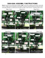
5000-028A ASSEMBLY INSTRUCTIONS
(JD 616C & 716C)
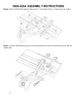
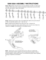
Step 1:
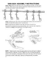
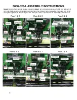
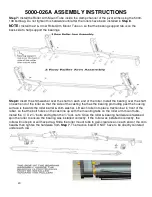
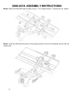
Attach the 5000-202 mount brackets to the frame using the 5/8 x 6 bolts, mounting straps, & 5/8”
lock hex nuts. Mounting Brackets will be located under the snouts between rows 1 & 2, 2 & 3, 4 & 5, 5 &
6, 7 & 8, 8 & 9, 10 & 11, and 11 & 12. Slide the mount bracket up so the deck plate adjustment rod is
located in the cut out of the mount bracket.
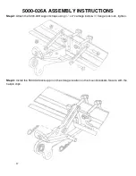
If corn head is equipped with protective shield (like pic with
the arrow shows), you can either: remove each shield, cut a notch in each shield, or bend each shield
upwards to gain clearance. The shields on a 90 series head will need removed.
Note:
Do not fully tighten hardware until
Step 6
after all of the pivot arms & springs are installed.
Arrows indicate 5000-202 mount bracket locations
Содержание 5000-025A
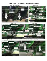
Страница 35: ...35 5000 034 ASSEMBLY INSTRUCTIONS Row 1 2 and 2 3 Row 4 5 Row 5 6 Row 7 8 Row 8 9 Row 10 11 and 11 12 ...
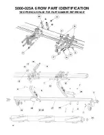
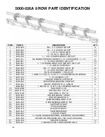
Страница 39: ...39 5000 025A 6 ROW PART IDENTIFICATION SEE PREVIOUS PAGE FOR PART NUMBER REFERENCE ...
Страница 41: ...41 5000 026A 8 ROW PART IDENTIFICATION SEE PREVIOUS PAGE FOR PART NUMBER REFERENCE ...
Страница 43: ...43 5000 027A 12 ROW PART IDENTIFICATION SEE PREVIOUS PAGE FOR PART NUMBER REFERENCE ...
Страница 45: ...45 5000 028A 16 ROW PART IDENTIFICATION SEE PREVIOUS PAGE FOR PART NUMBER REFERENCE ...
Страница 49: ...49 ...
Страница 50: ...50 ...
Страница 52: ...52 2565 785_Rev_D 12 2018 ...

