14
5000-025A ASSEMBLY INSTRUCTIONS
Step 6:
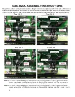
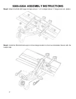
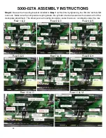
Secure the mounting bracket installed in
Step 1
at this time by tightening the 5/8 X 6” bolts & 5/8 lock nuts.
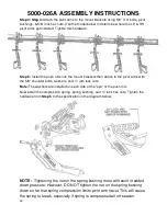
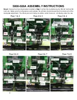
Make sure the compression spring clears the cylinder channel as well as the rocker arm of the deck plate adjust-
ment. The offset pivot arm clamp (5000-256 & 5000-259) should be under the snout, not directly under the row.
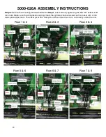
Row 1 & 2
Row 2 & 3
Row 4 & 5
Row 5 & 6
Note:
On 12 row heads installing on wheel tracks only, the top pictures on this page will illustrate
rows 4 & 5 and 5 & 6. The bottom pictures on this page will illustrate rows 7 & 8 and 8 & 9.
Note:
On 16 row heads installing on wheel tracks only, the top pictures on this page will illustrate
rows 6 & 7 and 7 & 8. The bottom pictures on this page will illustrate rows 9 & 10 and 10 & 11.
Содержание 5000-025A
Страница 35: ...35 5000 034 ASSEMBLY INSTRUCTIONS Row 1 2 and 2 3 Row 4 5 Row 5 6 Row 7 8 Row 8 9 Row 10 11 and 11 12 ...
Страница 39: ...39 5000 025A 6 ROW PART IDENTIFICATION SEE PREVIOUS PAGE FOR PART NUMBER REFERENCE ...
Страница 41: ...41 5000 026A 8 ROW PART IDENTIFICATION SEE PREVIOUS PAGE FOR PART NUMBER REFERENCE ...
Страница 43: ...43 5000 027A 12 ROW PART IDENTIFICATION SEE PREVIOUS PAGE FOR PART NUMBER REFERENCE ...
Страница 45: ...45 5000 028A 16 ROW PART IDENTIFICATION SEE PREVIOUS PAGE FOR PART NUMBER REFERENCE ...
Страница 49: ...49 ...
Страница 50: ...50 ...
Страница 52: ...52 2565 785_Rev_D 12 2018 ...


