25
5000-027A ASSEMBLY INSTRUCTIONS
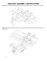
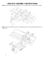
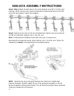
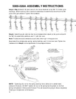
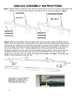
Step 7:
Install the Roller Arm Mount Tube inside the clamp channel of the pivot arms using the 5000-
138 bolt bag. Do not tighten this hardware until after the rollers have been installed in
Step 8
.
NOTE:
Install the Roller Arm Mount Tube on so that the bearing support tab is on the back side to
help support the bearings.
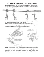
Step 8:
Insert the shim washer over the shaft on each end of the roller. Install the bearing over the
shaft on each end of the roller so that the side of the casting that has the bearing protruding past the
housing surface is towards the roller barrel & shim washer. Lift each roller into place, traction bar in
front of the rebar, so that the bolt holes on the cast line up with the mounting tabs on the roller arm
mount tube. Install the ½” X 2 ½” bolts and tighten the ½” lock nuts. Once the roller & bearing
hardware is fastened, spin the roller to ensure the bearing was installed correctly. If the roller was
installed incorrectly, the roller will not spin or will have drag. Slide the roller mount tube to gain
clearance on each end of the corn head & then tighten the hardware from
Step 7
. The traction bars
DO NOT have to be directly under the row.
Содержание 5000-025A
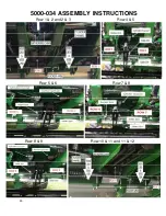
Страница 35: ...35 5000 034 ASSEMBLY INSTRUCTIONS Row 1 2 and 2 3 Row 4 5 Row 5 6 Row 7 8 Row 8 9 Row 10 11 and 11 12 ...
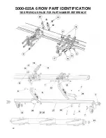
Страница 39: ...39 5000 025A 6 ROW PART IDENTIFICATION SEE PREVIOUS PAGE FOR PART NUMBER REFERENCE ...
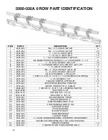
Страница 41: ...41 5000 026A 8 ROW PART IDENTIFICATION SEE PREVIOUS PAGE FOR PART NUMBER REFERENCE ...
Страница 43: ...43 5000 027A 12 ROW PART IDENTIFICATION SEE PREVIOUS PAGE FOR PART NUMBER REFERENCE ...
Страница 45: ...45 5000 028A 16 ROW PART IDENTIFICATION SEE PREVIOUS PAGE FOR PART NUMBER REFERENCE ...
Страница 49: ...49 ...
Страница 50: ...50 ...
Страница 52: ...52 2565 785_Rev_D 12 2018 ...


