background image


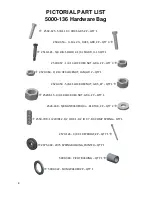
PICTORIAL PART LIST 


BEFORE INSTALLATION BEGINS, PLEASE CHECK THAT ALL PARTS WERE 

RECEIVED BY GOING THROUGH THE CRATE AND SORTING THE PARTS!!! 


5000-025A for JD 606C, 643, 693, 706C, (wheel tracks only) 612C, 712, 1243, 1293, 616C, & 716 Parts List


4) 5000-136, 4) 5000-138, 4) 5000-139, 4) 5000-202, 1) 5000-211A, 1) 5000-212A, 2) 5000-254, 2) 5000-256, 
2) 5000-259, 4) 5000-355 


5000-026A for JD 608C, 708C, 843, & 893 Parts List 

– 6) 5000-136, 6) 5000-138, 6) 5000-139, 6) 5000-202, 

1) 5000-203A, 1) 5000-211A, 1) 5000-212A, 2) 5000-254, 1) 5000-255, 3) 5000-256, 3) 5000-259, 2) 5000-301, 
6) 5000-355 


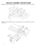
5000-027A for JD 612C, 712C, 1243, & 1293 Parts List 

– 8) 5000-136, 8) 5000-138, 8) 5000-139, 8) 5000-

202, 2) 5000-211A, 2) 5000-212A, 4) 5000-254, 4) 5000-256, 4) 5000-259, 2) 5000-301, 8) 5000-355 


5000-028A for JD 616C & 716C Parts List 

– 12) 5000-136, 12) 5000-138, 12) 5000-139, 12) 5000-202, 2) 

5000-203, 2) 5000-211A, 2) 5000-212A, 4) 5000-254, 2) 5000-255, 6) 5000-256, 6) 5000-259, 12) 5000-355 


5000-034 for JD 612FC & 712FC Folding Parts List 

– 8) 5000-136, 8) 5000-138, 8) 5000-139, 1) 5000-141, 

4) 5000-202, 2) 5000-211A, 2) 5000-212A, 4) 5000-254, 4) 5000-256, 4) 5000-259, 4) 5000-263, 8) 5000-355 


5000-080 – 5” Extension Kit Parts List (Optional) 

– 2) 2502-363 – ½” X 4 ½” GR 5 Bolts, 2) 2502-365 – ½”-

13 X 3 ¾” GR 5 Bolts, 6) 2520-357 – ½” Lock Nuts, 2) 5000-378 Spacer Bushings, 2) 5000-393 5” Extension 
Plates, & 2) 5000-394 Short Spacers 


5000-082 – 2” Lift Kit Parts List (Optional) 

– 2) 5000-408 Extender Plate, 1) 5000-409 Connector Pin 


5000-083 – 6 Row Devastator Lock Up Kit (Optional)

 – 1) 5000-161Hardware Bag, 1) 5000-430 Lock Pin 


5000-084 – 8/12 Row Devastator Lock Up Kit (Optional)

 – 1) 5000-162 Hardware Bag, 2) 5000-430 Lock Pin 

5000-202 


5000-203A -48” 


5000-211A -76”


5000-212A -76”


5000-254 – 80”


5000-255- 52” 


5000-256 (LH) 


5000-259 (RH)


5000-355 


5000-136 


5000-301 


2550-059


5000-139 


5000-138 


5000-080 


OPTIONAL 

ONLY USED ON 

893 & 1293 

5000-141 


5000-263 


Содержание 5000-025A

Страница 1: ...John Deere Model Corn Heads 606C 643 693 706C 608C 843 893 708C 612C 612FC Folding 712C 1243 1293 616C 716C OWNER S MANUAL PART IDENTIFICATION 2565 785_Rev_D 12 2018 YETTER MANUFACTURING CO Founded 1930 Colchester IL 62326 Toll free 800 447 5777 Fax 309 776 3222 Website yetterco com E mail info yetterco com ...

Страница 2: ...formation 4 6 Pictorial Part List 7 9 Bolt Torque Tools Required 10 Assembly Instructions 11 36 5000 025A 11 15 5000 026A 16 20 5000 027A 21 25 5000 028A 26 31 5000 034 32 36 Operation Maintenance Lock Up 37 Part Identification 38 48 Troubleshooting 51 ...

Страница 3: ...roduct according to the maintenance schedule in the operator s manual The user is responsible for inspecting his machine and for having parts repaired or replaced when continued use of the product would cause damage or excessive wear to the other parts It is the user s responsibility to deliver his machine to the Yetter dealer who sold him the product for service or replacement of defective parts ...

Страница 4: ...l attention to the caution notes in the text Review this manual at least once a year with all operators 1 Read and understand the operator s manual before operating this machine Failure to do so is considered a misuse of the equipment 2 Make sure equipment is secure before operating 3 Always keep children away from equipment when operating 4 Make sure everyone that is not directly involved with th...

Страница 5: ...ad to combine lock head to combine 2 Raise the head off the ground and engage safety stop on the feeder house cylinder 3 Apply combine parking brake turn off combine engine and remove the key 4 Wear personal protective equipment during installation steel toe footwear safety glasses gloves FOLLOW ALL INSTRUCTIONS GIVEN BY THE COMBINE MANUFACTURER ...

Страница 6: ...e combine manufacturer generally keeps corresponding kits readily available for dealers Subject to the design of the corn header and the carrying capacity of different combines the steering axle may require the fitting of additional weights and the rear tires be filled with ballast FOLLOW ALL INSTRUCTIONS GIVEN BY THE COMBINE MANUFACTURER ...

Страница 7: ...00 139 12 5000 202 2 5000 203 2 5000 211A 2 5000 212A 4 5000 254 2 5000 255 6 5000 256 6 5000 259 12 5000 355 5000 034 for JD 612FC 712FC Folding Parts List 8 5000 136 8 5000 138 8 5000 139 1 5000 141 4 5000 202 2 5000 211A 2 5000 212A 4 5000 254 4 5000 256 4 5000 259 4 5000 263 8 5000 355 5000 080 5 Extension Kit Parts List Optional 2 2502 363 X 4 GR 5 Bolts 2 2502 365 13 X 3 GR 5 Bolts 6 2520 35...

Страница 8: ...NUT GR A ZP QTY 3 2520 364 1 2 13 HEX LOCKNUT JAM GR 2 QTY 1 2520 459 5 8 11 LOCK HEX NUT GR 5 ZP QTY 1 2520 515 3 4 10 LOCK HEX NUT GR A ZP QTY 1 2526 449 5 8FLATWASHER1 4 010 THK ZP QTY 2 2550 709 1 2 WIRE 2 1 2 OD X 1 1 2 ID X 7 1 4 COMP SPRING QTY 1 2570 126 3 4 X 10 EYEBOLT ZP QTY 1 2975 302 2975 SPRING BUSHING PAINTED QTY 1 5000 318 PIVOT BUSHING QTY 1 5000 322 SHIM WASHER ZP QTY 1 ...

Страница 9: ...CER BUSHING QTY 2 2502 352 5 8 11 X 6 HHCS GRADE 8 ZP QTY 4 2505 345 1 2 13 X 2 CAR BLT GR5 ZP QTY 2 2520 361 1 2 13FLANGE WHZLCK HXNT GR 5 ZP QTY 2 2570 465 7 GA HAIRPIN COTTER ZP QTY 2 2520 459 5 8 11 LOCK HEX NUT GR A ZP QTY 4 5000 309 SUPPORT STRAP QTY 2 5000 319 MOUNT STRAP 3 QTY 2 5000 323 LOCK UP PIN ZP QTY 1 2505 414 5 8 11 X 6 CARRIAGE BOLT GR 5 ZP QTY 2 5000 402 WEDGE QTY 2 ...

Страница 10: ...sure to replace it with hardware of equal size strength and thread type Refer to the torque values chart when tightening hardware The chart below is a guide for proper torque Use it unless a specified torque is called out elsewhere in the manual Torque is the force applied to the end of the handle or cheater bar times the length of the handle or bar Use a torque wrench wherever possible The follow...

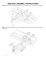
Страница 11: ...orn head is equipped with protective shield like pic with the arrow shows you can either remove each shield cut a notch in each shield or bend each shield upwards to gain clearance The shields on a 90 series head will need removed Note Do not fully tighten hardware until Step 6 after all of the pivot arms springs are installed 6 Row Arrows indicate 5000 202 mount bracket locations 12 Row Wheel Tra...

Страница 12: ...Y INSTRUCTIONS Step 2 Attach the 5000 309 support straps using x 2 carriage bolts flange lock nuts tighten Step 3 Install the 5000 323 lock up pin in the storage location on the mount brackets Secure with the hairpin clips ...

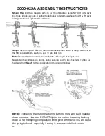
Страница 13: ...oulder bolts washers and jam lock nuts Note The washers are installed on each side of the eye of the push rod Now install the compression spring spring bushing and lock hex nuts Tighten the hardware from Step 5 to the specification in the diagram below NOTE Tightening the nut on the spring bushing more will result in added down pressure However DO NOT tighten the nut on the spring bushing down so ...

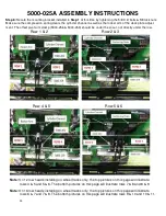
Страница 14: ...ot arm clamp 5000 256 5000 259 should be under the snout not directly under the row Row 1 2 Row 2 3 Row 4 5 Row 5 6 Note On 12 row heads installing on wheel tracks only the top pictures on this page will illustrate rows 4 5 and 5 6 The bottom pictures on this page will illustrate rows 7 8 and 8 9 Note On 16 row heads installing on wheel tracks only the top pictures on this page will illustrate row...

Страница 15: ...the side of the casting that has the bearing protruding past the housing surface is towards the roller barrel shim washer Lift each roller into place traction bar in front of the rebar so that the bolt holes on the cast line up with the mounting tabs on the roller arm mount tube Install the X 2 bolts tighten the lock nuts Once the roller bearing hardware is fastened spin the roller to ensure the b...

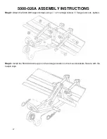
Страница 16: ... the cut out of the mount bracket On JD 893 corn heads use the 5000 301 L Clamp Plate with the mounting brackets between rows 1 2 and 7 8 If corn head is equipped with protective shield like pic with the arrow shows you can either remove each shield cut a notch in each shield or bend each shield upwards to gain clearance The shields on a 90 series head will need removed Note Do not fully tighten h...

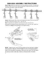
Страница 17: ...Y INSTRUCTIONS Step 2 Attach the 5000 309 support straps using x 2 carriage bolts flange lock nuts tighten Step 3 Install the 5000 323 lock up pin in the storage location on the mount brackets Secure with the hairpin clips ...

Страница 18: ...shoulder bolts washers and jam lock nuts Note The washers are installed on each side of the eye of the push rod Now install the compression spring spring bushing and lock hex nuts Tighten the hardware from Step 5 to the specification in the diagram below NOTE Tightening the nut on the spring bushing more will result in added down pressure However DO NOT tighten the nut on the spring bushing down s...

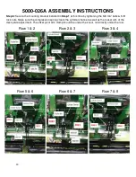
Страница 19: ...is time by tightening the 5 8 X 6 bolts 5 8 lock nuts Make sure the compression spring clears the cylinder channel as well as the rocker arm of the deck plate adjustment The offset pivot arm clamp should be under the snout not directly under the row Row 1 2 Row 2 3 Row 3 4 Row 5 6 Row 6 7 Row 7 8 ...

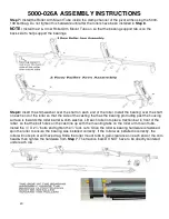
Страница 20: ...t the side of the casting that has the bearing protruding past the housing surface is towards the roller barrel shim washer Lift each roller into place traction bar in front of the rebar so that the bolt holes on the cast line up with the mounting tabs on the roller arm mount tube Install the X 2 bolts and tighten the lock nuts Once the roller bearing hardware is fastened spin the roller to ensure...

Страница 21: ... is located in the cut out of the mount bracket On JD 1293 corn heads use the 5000 301 L Clamp Plate with the mounting brackets between rows 2 3 and 10 11 If corn head is equipped with protective shield like pic with the arrow shows you can either remove each shield cut a notch in each shield or bend each shield upwards to gain clearance The shields on a 90 series head will need removed Note Do no...

Страница 22: ...Y INSTRUCTIONS Step 2 Attach the 5000 309 support straps using x 2 carriage bolts flange lock nuts tighten Step 3 Install the 5000 323 lock up pin in the storage location on the mount brackets Secure with the hairpin clips ...

Страница 23: ...shoulder bolts washers and jam lock nuts Note The washers are installed on each side of the eye of the push rod Now install the compression spring spring bushing and lock hex nuts Tighten the hardware from Step 5 to the specification in the diagram below NOTE Tightening the nut on the spring bushing more will result in added down pressure However DO NOT tighten the nut on the spring bushing down s...

Страница 24: ... tightening the 5 8 X 6 bolts 5 8 lock nuts Make sure the compression spring clears the cylinder channel as well as the rocker arm of the deck plate adjustment The offset pivot arm clamp should be under the snout not directly under the row Row 1 2 Row 2 3 Row 4 5 Row 5 6 Row 7 8 Row 8 9 Row 10 11 Row 11 12 ...

Страница 25: ...at the side of the casting that has the bearing protruding past the housing surface is towards the roller barrel shim washer Lift each roller into place traction bar in front of the rebar so that the bolt holes on the cast line up with the mounting tabs on the roller arm mount tube Install the X 2 bolts and tighten the lock nuts Once the roller bearing hardware is fastened spin the roller to ensur...

Страница 26: ...ount bracket up so the deck plate adjustment rod is located in the cut out of the mount bracket If corn head is equipped with protective shield like pic with the arrow shows you can either remove each shield cut a notch in each shield or bend each shield upwards to gain clearance The shields on a 90 series head will need removed Note Do not fully tighten hardware until Step 6 after all of the pivo...

Страница 27: ...Y INSTRUCTIONS Step 2 Attach the 5000 309 support straps using x 2 carriage bolts flange lock nuts tighten Step 3 Install the 5000 323 lock up pin in the storage location on the mount brackets Secure with the hairpin clips ...

Страница 28: ...shoulder bolts washers and jam lock nuts Note The washers are installed on each side of the eye of the push rod Now install the compression spring spring bushing and lock hex nuts Tighten the hardware from Step 5 to the specification in the diagram below NOTE Tightening the nut on the spring bushing more will result in added down pressure However DO NOT tighten the nut on the spring bushing down s...

Страница 29: ...is time by tightening the 5 8 X 6 bolts 5 8 lock nuts Make sure the compression spring clears the cylinder channel as well as the rocker arm of the deck plate adjustment The offset pivot arm clamp should be under the snout not directly under the row Row 1 2 Row 2 3 Row 3 4 Row 5 6 Row 6 7 Row 7 8 ...

Страница 30: ...e by tightening the 5 8 X 6 bolts 5 8 lock nuts Make sure the compression spring clears the cylinder channel as well as the rocker arm of the deck plate adjustment The offset pivot arm clamp should be under the snout not directly under the row Row 9 10 Row 10 11 Row 11 12 Row 13 14 Row 14 15 Row 15 16 ...

Страница 31: ...o that the side of the casting that has the bearing protruding past the housing surface is towards the roller barrel shim washer Lift each roller into place traction bar in front of the rebar so that the bolt holes on the cast line up with the mounting tabs on the roller arm mount tube Install the X 2 bolts and tighten the lock nuts Once the roller bearing hardware is fastened spin the roller to e...

Страница 32: ... between rows 1 2 and 2 3 will use 5 8 X 6 bolts mounting straps 5 8 lock nuts The 5000 263 mounts between rows 10 11 and 11 12 will each use 3 5 8 X 6 bolts 1 5 8 X 6 Carriage bolts 1 used on the top left of each mount on these rows mounting straps and 5 8 lock nuts Slide the mount bracket up so the deck plate adjustment rod is located in the cut out of the mount bracket Note Do not fully tighten...

Страница 33: ... INSTRUCTIONS Step 2 Attach the 5000 309 support straps using x 2 carriage bolts flange lock nuts tighten Step 3 Install the 5000 323 lock up pin in the storage location on the mount brackets Secure with the hairpin clips ...

Страница 34: ... eye of the push rod Now install the compression spring spring bushing and lock hex nuts The 5000 402 wedge will need installed between the compression spring and the mount bracket between rows 1 2 and 2 3 to keep the spring from contacting the gathering chains Tighten the hardware from Step 5 to the specification in the diagram below NOTE Tightening the nut on the spring bushing more will result ...

Страница 35: ...35 5000 034 ASSEMBLY INSTRUCTIONS Row 1 2 and 2 3 Row 4 5 Row 5 6 Row 7 8 Row 8 9 Row 10 11 and 11 12 ...

Страница 36: ...t the housing surface is towards the roller barrel shim washer Lift each roller into place traction bar in front of the rebar so that the bolt holes on the cast line up with the mounting tabs on the roller arm mount tube Install the X 2 bolts and tighten the lock nuts Once the roller bearing hardware is fastened spin the roller to ensure the bearing was installed correctly If the roller was instal...

Страница 37: ... vice use a pry bar to turn the bearing in the housing parallel with the slots remove the old bearing apply anti seize lubricant to the interior of the bearing housing insert the new bearing in the slots use a pry bar to move back to position Wobble the bearing around to help work the lubricant into the outer race of the bearing STORAGE When storing the corn head for the offseason it is OK for the...

Страница 38: ...THICK ZP 8 13 2550 709 WIRE 2 1 2 OD X 1 1 2 ID X 7 1 4 COMPRESSION SPRING 4 14 2570 126 X 10 EYEBOLT ZP 4 15 2570 465 7 GAUGE HAIRPIN COTTER ZP 8 16 2975 302 2975 SPRING BUSHING PAINTED 4 17 5000 202 MOUNT BRACKET W A SINGLE 4 2528 369 1 380 OD X 1 00 ID X 1 25 L BEARING SLEEVE 18 5000 309 SUPPORT STRAP 8 19 5000 318 PIVOT BUSHING 4 20 5000 319 MOUNT STRAP 3 8 21 5000 322 SHIM WASHER ZP 4 22 5000...

Страница 39: ...39 5000 025A 6 ROW PART IDENTIFICATION SEE PREVIOUS PAGE FOR PART NUMBER REFERENCE ...

Страница 40: ... 4 COMPRESSION SPRING 6 14 2570 126 X 10 EYEBOLT ZP 6 15 2570 465 7 GAUGE HAIRPIN COTTER ZP 12 16 2975 302 2975 SPRING BUSHING PAINTED 6 17 5000 202 MOUNT BRACKET W A SINGLE 6 2528 369 1 380 OD X 1 00 ID X 1 25 L BEARING SLEEVE 18 5000 203A ROLLER W A 48 1 19 5000 211A ROLLER W A LH 76 1 20 5000 212A ROLLER W A RH 76 1 21 5000 254 ROLLER MOUNT 3 ROW 2 22 5000 255 ROLLER MOUNT W A 1 23 5000 256 OVE...

Страница 41: ...41 5000 026A 8 ROW PART IDENTIFICATION SEE PREVIOUS PAGE FOR PART NUMBER REFERENCE ...

Страница 42: ...WIRE 2 1 2 OD X 1 1 2 ID X 7 1 4 COMPRESSION SPRING 8 14 2570 126 X 10 EYEBOLT ZP 8 15 2570 465 7 GAUGE HAIRPIN COTTER ZP 16 16 2975 302 2975 SPRING BUSHING PAINTED 8 17 5000 202 MOUNT BRACKET W A SINGLE 8 2528 369 1 380 OD X 1 00 ID X 1 25 L BEARING SLEEVE 18 5000 309 SUPPORT STRAP 16 19 5000 318 PIVOT BUSHING 8 20 5000 319 MOUNT STRAP 3 16 21 5000 322 SHIM WASHER ZP 8 22 5000 323 LOCK UP PIN ZP ...

Страница 43: ...43 5000 027A 12 ROW PART IDENTIFICATION SEE PREVIOUS PAGE FOR PART NUMBER REFERENCE ...

Страница 44: ... 2 OD X 1 1 2 ID X 7 1 4 COMPRESSION SPRING 12 14 2570 126 X 10 EYEBOLT ZP 12 15 2570 465 7 GAUGE HAIRPIN COTTER ZP 24 16 2975 302 2975 SPRING BUSHING PAINTED 12 17 5000 202 MOUNT BRACKET W A SINGLE 12 2528 369 1 380 OD X 1 00 ID X 1 25 L BEARING SLEEVE 18 5000 203A ROLLER W A 48 2 19 5000 211A ROLLER W A LH 76 2 20 5000 212A ROLLER W A RH 76 2 21 5000 254 ROLLER MOUNT 3 ROW 4 22 5000 255 ROLLER M...

Страница 45: ...45 5000 028A 16 ROW PART IDENTIFICATION SEE PREVIOUS PAGE FOR PART NUMBER REFERENCE ...

Страница 46: ...4 2550 709 WIRE 2 1 2 OD X 1 1 2 ID X 7 1 4 COMPRESSION SPRING 8 15 2570 126 X 10 EYEBOLT ZP 8 16 2570 465 7 GAUGE HAIRPIN COTTER ZP 16 17 2975 302 2975 SPRING BUSHING PAINTED 8 18 5000 202 MOUNT BRACKET W A SINGLE 4 2528 369 1 380 OD X 1 00 ID X 1 25 L BEARING SLEEVE 19 5000 211A ROLLER W A LH 76 2 20 5000 212A ROLLER W A RH 76 2 21 5000 254 ROLLER MOUNT 3 ROW 4 22 5000 256 OVER BEARING ARM 19 LH...

Страница 47: ...6 2505 414 5 8 11 X 6 CARRIAGE BOLT GR 5 USED ON ROWS 10 11 11 12 2 9 2520 361 13 FLANGE WHIZLOCK NUT GR 5 16 11 2520 459 5 8 11 LOCK HEX NUT GR B 40 16 2570 465 7 GAUGE HAIRPIN COTTER 16 18 5000 202 MOUNT BRACKET W A SINGLE 4 2528 369 1 380 OD X 1 00 ID X 1 25 L BEARING SLEEVE 8 24 5000 263 MOUNT BRACKET W A 4 25 5000 309 SUPPORT STRAP 16 27 5000 319 MOUNT STRAP 3 16 29 5000 323 LOCK UP PIN 8 ...

Страница 48: ... HEX NUT 8 13 2526 449 5 8 FLAT WASHER 16 14 2550 709 WIRE 2 OD X 1 ID X 7 COMPRESSION SPRING 8 15 2570 126 X 10 EYEBOLT ZP 8 17 2975 302 2975 SPRING BUSHING 8 19 5000 211A ROLLER W A LH 76 2 20 5000 212A ROLLER W A RH 76 2 21 5000 254 ROLLER MOUNT 3 ROW 4 22 5000 256 OVER BEARING ARM 19 LH 6 23 5000 259 OVER BEARING ARM 19 RH 2 26 5000 318 PIVOT BUSHING 8 28 5000 322 SHIM WASHER 8 30 5000 355 1 D...

Страница 49: ...49 ...

Страница 50: ...50 ...

Страница 51: ...earing that protrudes outside of the cast housing is facing toward the roller each roller should spin freely by hand 5 Order the 5000 080 Set Back Kit order 2 per roller 6 Back the nut off of the push rod until the nut is flush Stalk aren t devastated 1 Insufficient spring down pressure 2 Operating corn head too high 1 Tighten push rod nut on spring bushing more 2 Lower corn head until the rollers...

Страница 52: ...52 2565 785_Rev_D 12 2018 ...

Отзывы: