


Allowable load for wrist axis and wrist flange
7
-
44
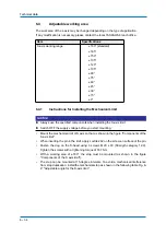
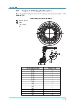
Keep the centroidal distance of the load/mass within the specifications; refer to the fig.:
Moment of arm rating
Moment of arm rating
P point
T-axes rotation center line
B-axes rotation centre line
All dimensions in mm
P point
R-, T-axes rotation centre
line
B-axes rotation centre line
All dimensions in mm
1
346
247
216
400
300
200
100
LB(mm)
204
145
300
200
127
100
LT(mm)
5kg
7kg
2
3
1
400
800
1200
200
600
1000
1049
742
500
375
300
LB [mm]
400
800
1200
1600
0
1800
1400
1000
600
200
175
1673
1100
733
550
440
W=10
W=20
W=30
W=40
W=50
LT [mm]
2
3