


68
APPENDIX 1 SPECIFICATIONS
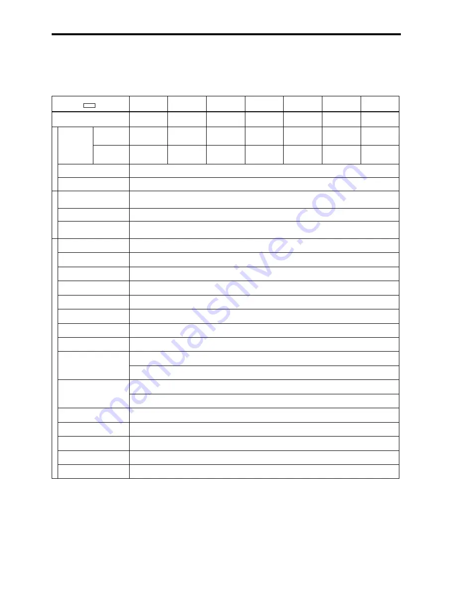
Table A
−
1
Specifications
Model
CIMR
−
G5C
51P5
52P2
53P7
55P5
57P5
5011
5015
Max. Applicable Motor Output *
kW
1.5
2.2
3.7
5.5
7.5
11
15
istics Rated Output
Constant
Torque
3.5
4.1
6.3
9.8
12.5
17
22
C
haracteri
s Rated Output
Current (A)
Variable
Torque
3.9
4.6
7
11
14
19
25
ut
put
C
h
Max. Output Voltage
3
−
Phase 500/525/575/600 V (Proportional to input voltage)
Out
p
Rated Output Frequency
Up to 400 Hz available by programming
pp
ly
Rated Input Voltage and
Frequency
3
−
Phase 500/525/575/600 V 50/60 Hz
w
er
Su
p
Allowable Voltage Fluctuation
+10%,
−
15%
Pow
e
Allowable Frequency
Fluctuation
¦
5%
Control Method
Sine wave PWM
Starting Torque
150% / 1 Hz (150% / 0 r / min with PG)
[
Speed Control Range
1:100 (1:1000 with PG)
[
Speed Control Accuracy
¦
0.2% (
¦
0.02% with PG)
[
Speed Response
5 Hz (30 Hz with PG)
[
Torque Limit
Available (4 quadrants can be changed by parameter setting.)
cs
Torque Accuracy
¦
5%
cteristic
s
Frequency Control Range
0.1 to 400 Hz
C
harac
t
Frequency Accuracy
Digital command :
¦
0.01% (
−
10
°
C to +40
°
C)
ontrol
C Frequency Accuracy
Analog command :
¦
0.1% (25
°
C
¦
10
°
C)
C
o
Frequency Resolution
Digital operator reference :
¦
0.01 Hz
Frequency Resolution
Analog reference :
¦
0.03 Hz/60 Hz (11 bit + code)
Output Frequency Resolution
0.001 Hz
Overload Capacity
150% of rated output current for 1 minute
Frequency Setting Signal
−
10 to 10 V, 0 to 10 V, 4 to 20 mA
Accel/Decel Time
0.01 to 6000.0 sec (Accel/decel time setting independently, 4 steps available)
Braking Torque
Approx. 20%
(Cont’d)
* Based on a YASKAWA standard 4
−
pole motor for max. applicable motor output.
[
Occasional tuning may be required.