background image

INSTALLATION

Arc-WorldLite 50 System Manual

4-4

MOTO

MAN

4.4

Leveling and Securing the Cell

After everything is in position, the equipment should be leveled and then secured
to the floor. The lag bolts are shipped in the accessories box. Refer to your
Motoman Robot manipulator manual for floor loading requirements. To level and
secure the equipment, proceed as follows:

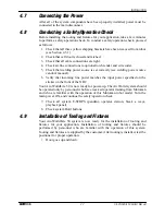
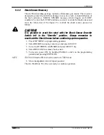
1. Level cell base by adjusting leveling bolts (see Figure 4-4).
2. Insert a 1/2-in. concrete drill bit through center of the leveling bolts and drill

holes for lag bolts.

3. Vacuum concrete dust from holes.
4. Using lag bolts supplied, lag Arc-WorldLite 50 common base to floor.


Figure 4-4   Location of Leveling Bolts

4.5

Connecting the Cables

After components are level and securely in place, the cables should be unwrapped
from around the equipment and laid out according to the cable diagram included in
the system drawing package. Each cable connection is clearly identified for ease of
installation.

CAUTION!

Route wires and cables away from hazardous work areas to avoid
wire breakage and unnecessary interruption of cell operation.

4.5.1

Connecting the Earth Ground

The robot and the XRC must each be connected to an earth ground. An earth
ground is a ground in which the equipment is connected to a ground stake driven
into the earth. The ground stake must be driven a minimum of eight feet into the
earth, and the earth must be treated with chemicals in order to reduce resistance to
the ground stake. Deeper ground stakes may be required depending on area soil
conditions. A maximum of 100 ohms ground resistance is recommended. To
ground the robot and the XRC, proceed as follows:

LEVELING BOLT

A

V

PO

WE

R

ALA

RM

ON

OFF

CO

NTR

OL

PO

WE

R

AM

ME

TER

VO

LTM

ETE

R

0

_

ON

OFF

ON

OFF

CO


MA

G

FLO

W

AUTO

SOLO 
FON

Ø16

Ø14

Ø12

GAS 

FLO

W

WIRE

 DIA

WIRE

 TY

PE

GAS

PEN

ETR

ATIO

N

CRAT

ER

ALAR

M

IND

ICA

TOR

CUR

REN

T

INP

UT

CABL

E

HEAT

WATE

R

FUS

E

CRAT

ER V

OLTA

GE

CRAT

ER C

URR

ENT

SE

RV

ON

RE

AD

Y

RE

MO

TE

PL

AY

(O

FF

)

(O

N)

TE

AC

H

MO

DE

EM

ER

GE

NC

ST

OP

ED

IT

 L

OC

K

AL

AR

M

HO

LD

ST

AR

T

YA

SN

AC 

 XRC

  SK

16X

ON

T

R

IP

OP

E

N

/

R

O

F

F

W

ORLDLITE

WORLDLITE

by MOTOM

AN

by MOTOMAN

Содержание Motoman WorldLite-50

Страница 1: ...st Carrollton OH 45449 TEL 937 847 6200 FAX 937 847 6277 24 Hour Service Hotline 937 847 3200 QVQOCP 4 QPVTQNNGT TE 9QTNF KVG 5 UVGO CPWCN HQT 58 4QDQV Part Number 142719 1 Release Date July 25 2000 D...

Страница 2: ...produced or transmitted to other parties without the expressed written authorization of Motoman Inc 2003 by MOTOMAN All Rights Reserved Because we are constantly improving our products we reserve the...

Страница 3: ...2 3 2 4 Mechanical Safety Devices 2 3 2 5 Installation Safety 2 4 2 6 Programming Safety 2 4 2 7 Operation Safety 2 5 2 8 Maintenance Safety 2 6 3 EQUIPMENT DESCRIPTION 3 1 SV3X Robot Description 3 1...

Страница 4: ...Brackets 4 3 4 4 Leveling and Securing the Cell 4 4 4 5 Connecting the Cables 4 4 4 5 1 Connecting the Earth Ground 4 4 4 5 2 Connecting the Water Circulator Optional 4 5 4 6 Connecting the Gas Air S...

Страница 5: ...rea Needed for Installation 4 2 Figure 4 2 Unbolting the Arc WorldLite 50 Common Base 4 3 Figure 4 3 Location of Shipping Brackets 4 3 Figure 4 4 Location of Leveling Bolts 4 4 Figure 4 5 Water Circul...

Страница 6: ...Arc WorldLite 50 System Manual iv MOTOMAN NOTES...

Страница 7: ...Section 1 3 This manual contains the following sections SECTION 1 INTRODUCTION Provides general information about the Arc WorldLite 50 and its components a list of reference documents and customer se...

Страница 8: ...e all share a common base for ease of installation and to help maintain proper alignment between components The Arc WorldLite 50 cell is fully enclosed by sheet metal and weld curtains to protect the...

Страница 9: ...N E T R A T I O N C R A T E R A L A R M I N D I C A T O R C U R R E N T I N P U T C A B L E H E A T W A T E R F U S E C R A T E R V O L T A G E C R A T E R C U R R E N T SERVO ON READY REMOT E PLAY OF...

Страница 10: ...III Instruction Manual P N 132753 1 Vendor manuals for system components not manufactured by Motoman 1 4 Customer Service Information If you are in need of technical assistance contact the Motoman ser...

Страница 11: ...ram and maintain the robot cell The robot must not be operated by personnel who have not been trained We recommend that all personnel who intend to operate program repair or use the robot system be tr...

Страница 12: ...ate and imminent hazards that if not avoided will result in immediate serious personal injury or loss of life in addition to equipment damage WARNING Information appearing under the WARNING caption co...

Страница 13: ...ts and Outputs The robot must be placed in Emergency Stop E STOP mode whenever it is not in use In accordance with ANSI RIA R15 06 section 6 13 4 and 6 13 5 use lockout tagout procedures during equipm...

Страница 14: ...d with the operation of the equipment must understand potential dangers of operation Programming tips are as follows Any modifications to PART 1 of the controller PLC can cause severe personal injury...

Страница 15: ...uipment for proper operation Repair or replace any non functioning safety equipment immediately Inspect the robot and work envelope to ensure no potentially hazardous conditions exist Be sure the area...

Страница 16: ...hanges are made A backup must always be made before any servicing or changes are made to options accessories or equipment to avoid loss of information programs or jobs Do not enter the robot cell whil...

Страница 17: ...XRC Controller The XRC robotic controller see Figure 3 1 coordinates the operation of the Arc WorldLite 50 system It controls manipulator movement and welding power supply processes input and output s...

Страница 18: ...NOTE Changing modes from PLAY to TEACH during playback will cause the program to cease execution similar to HOLD to resume operation press PLAY and then START Remote This push button disables the play...

Страница 19: ...r more information refer to the manipulator manual that came with your system NOTE The programming pendant LCD display goes dark after a few minutes of inactivity Press any key to restore screen Figur...

Страница 20: ...RC WELDING GENERAL HANDLING and SPOT WELDING This icon allows you to select the applications available to the controller VARIABLE This icon accesses the display and editing menu for the arithmetic var...

Страница 21: ...on between the XRC and a floppy disk controller FC1 or FC2 FDE Floppy Disk Emulator software or other form of communication see Figure 3 4 Figure 3 4 RS 232C Serial Port ENABLE Switch The ENABLE switc...

Страница 22: ...tion 3 3 1 Cycle Start WARNING The operation of the CYCLE START palm button is dependent on the structure of the Master job Altering the Master job could result in injury to personnel or damage to the...

Страница 23: ...parts from the fixture NOTE In high humidity areas use surface protection to prevent corrosion of the tooling plate 3 4 1 Arc Shields WARNING Although the arc curtain blocks dangerous arc radiation n...

Страница 24: ...uses may be different For more specific information refer to the vendor manual that came with your system Figure 3 7 Power Sources WIRE FEEDER WIRE FEEDER 1 REMOTE CONTROL 10 AMP 10 AMP 115 V 9A 115...

Страница 25: ...olation of the power source analog signals NOTE Some power sources available with the Arc WorldLite 50 system do not use the UWI For more information specific to your system refer to the vendor manual...

Страница 26: ...vo power is removed from the system The system E STOP lights come on and all positioner motion is stopped The following is a list of their locations The playback panel on the controller has one E STOP...

Страница 27: ...ripheral devices The XRC has eight possible cubes available These cubes are internally tied to Specified Outputs R1 SOUT 081 104 Setup of these cubes is done at the factory prior to shipment However s...

Страница 28: ...EQUIPMENT DESCRIPTION Arc WorldLite 50 System Manual 3 12 MOTOMAN NOTES...

Страница 29: ...components 4 1 Materials Required All system hardware necessary for installing the Arc WorldLite 50 is included with the system This section identifies customer supplied items and tools required to c...

Страница 30: ...the Arc WorldLite 50 common base proceed as follows 1 Unbolt Arc WorldLite 50 common base from wooden shipping skid using a 3 4 in socket see Figure 4 2 WARNING The robot positioner common base weighs...

Страница 31: ...stem is in place remove all shipping brackets Figure 4 3 Location of Shipping Brackets SHIPPING BOLT LEVELING BOLT A V P O W E R A L A R M O N O F F C O N T R O L P O W E R A M M E T E R V O L T M E T...

Страница 32: ...to avoid wire breakage and unnecessary interruption of cell operation 4 5 1 Connecting the Earth Ground The robot and the XRC must each be connected to an earth ground An earth ground is a ground in...

Страница 33: ...able to earth ground stake 3 Connect one end of second earth ground cable to common ground bus bar inside XRC 4 Connect other end of second earth ground cable to earth ground stake 4 5 2 Connecting th...

Страница 34: ...ite 100 are already connected when the unit is shipped Gas and air services must be completed after the cell has been secured to the floor The gas and air connections are located in the back of the ce...

Страница 35: ...ource vendor s manual 6 Verify that incoming line power matches the input power specified on the sticker on the front of the XRC Your Arc WorldLite 50 is now ready for power up The ArcWorld system sho...

Страница 36: ...INSTALLATION Arc WorldLite 50 System Manual 4 8 MOTOMAN NOTES...

Страница 37: ...system Your system configuration and job structure may differ slightly from that presented here however basic operation will be the same Any changes made to your system configuration and or job struc...

Страница 38: ...me position and operator door lowers servo power is remover allowing the operator to unload parts 5 2 1 Start Up To start up the cell from a Power Off condition proceed as follows 1 Turn on main power...

Страница 39: ...Job list appears on display screen 3 Using cursor keys move cursor to Master job and press ENTER Master job appears in display screen 4 Make sure cursor is at top of the job 5 Press PLAY mode button o...

Страница 40: ...ESET F5 soft key on the programming pendant Major Alarms Major alarms are hardware failures Major alarms might occur because of a servo tracking error or an abnormal speed and are usually associated w...

Страница 41: ...as follows CAUTION It is possible to crash the robot with the Shock Sensor Override Switch left in the Override position Always remember to reactivate the Shock Sensor before continuing system operat...

Страница 42: ...OPERATION Arc WorldLite 50 System Manual 5 6 MOTOMAN NOTES...

Страница 43: ...tive antifreezes contain stop leak additives that will clog the small torch water cooling ports and damage the gaskets in the water circulator pump Table 6 1 Periodic Maintenance Frequency Component P...

Страница 44: ...nates circuit breaker F FU or 101FU designates fuse Table 6 2 Universal Welding Interface UWI Fuses Device Rating Part Location Purpose F1 8A 250V On KXA motor speed control Limits damage from shorts...

Страница 45: ...E Switch 3 5 3 10 Equipment Description 3 1 Error Messages 5 4 E STOP Recovery 5 4 F Fencing 3 10 Fuse and Circuit Breaker Protection 6 2 Fuses 6 2 G Gas Air Services Connecting 4 6 General Safeguardi...

Страница 46: ...Weld Table 3 7 Status Area 3 4 Symbol 1 Cycle Cycle Mode 3 4 Alarm System Status 3 4 Auto Cycle Mode 3 4 S continued Symbol Cylindrical Coordinate System 3 4 E Stop System Status 3 4 High Manual Spee...

Отзывы: