YASKAWA MOTOMAN DX100 Скачать руководство пользователя страница 172

3     Teaching
3.9  Other Job-editing Functions

3-89

155507-1CD

RE-CSO-A037

DX100

3.9.4.10 Manipulator 

Types

When the position data of the job data are described using the XYZ 
format, several postures may be taken according to the manipulator’s 
structure when moving it to the described position.  

Although these postures have the same coordinates for TCP, they vary in 
pulse for each axis. 

Thus, the manipulator’s posture cannot be uniquely defined only by the 
coordinate value, and it is necessary to specify the data other than the 
coordinate value to define the manipulator’s posture. 

This is called “Type”. 

Type varies according to the manipulator model. 
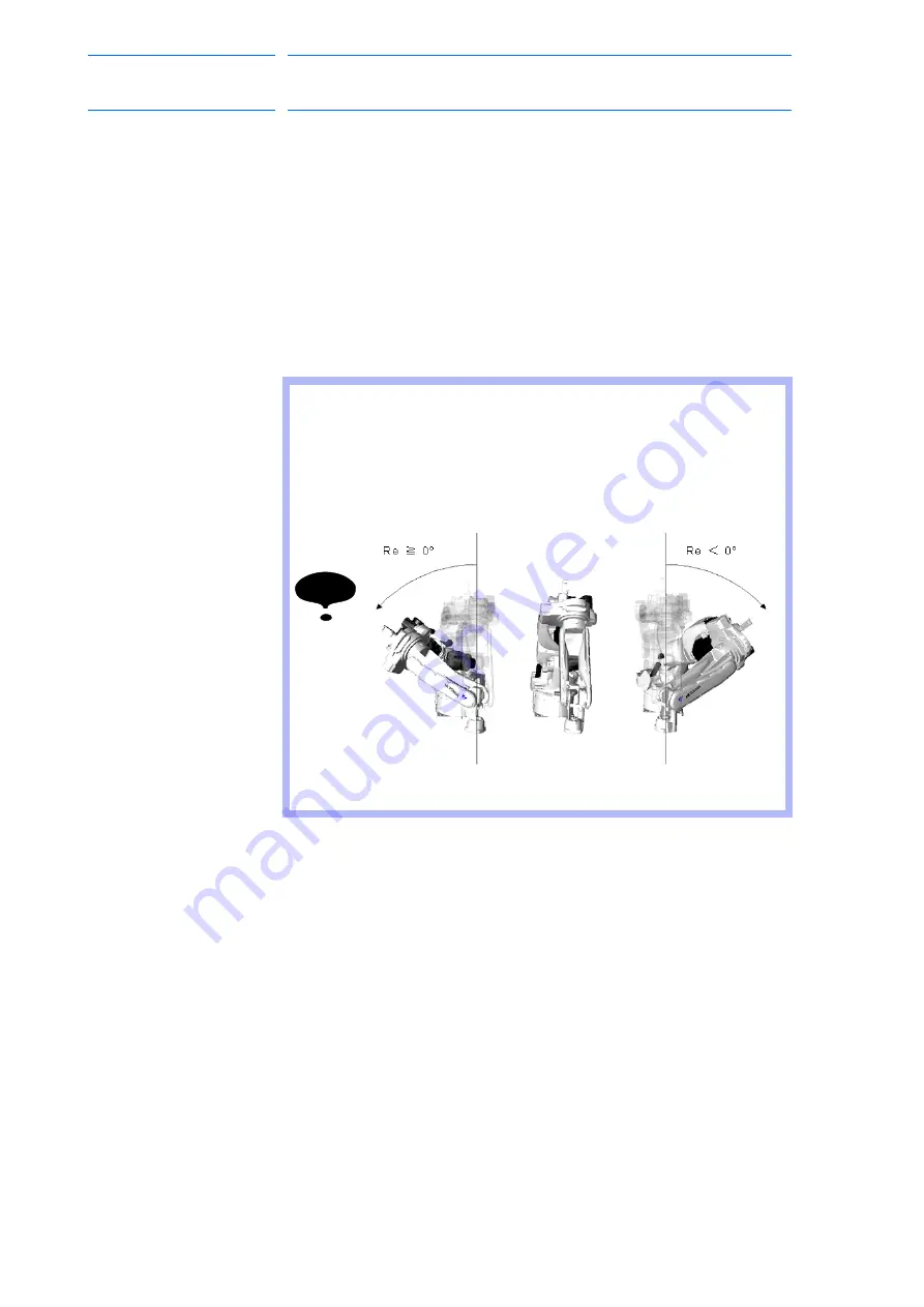
NOTE

For the manipulator with seven axes, X, Y, Z, Rx, Ry, Rz, Re 
and Type are used. 

Re is an element to indicate the posture of the manipulator 
with seven axes and does not change by the specified 
coordinates. 

The definition of Re is shown below. 

172 of 554

Содержание MOTOMAN DX100

Страница 1: ...Upon receipt of the product and prior to initial operation read these instructions thoroughly and retain for future reference MOTOMAN INSTRUCTIONS MOTOMAN INSTRUCTIONS DX100 INSTRUCTIONS DX100 OPERAT...

Страница 2: ...opyrighted property of Yaskawa and may not be sold or redistributed in any way You are welcome to copy this document to your computer or mobile device for easy access but you may not copy the PDF file...

Страница 3: ...laced before operating this product The drawings and photos in this manual are representative examples and differences may exist between them and the delivered product YASKAWA may modify this model wi...

Страница 4: ...ible for providing adequately trained personnel to operate program and maintain the equipment NEVER ALLOW UNTRAINED PERSONNEL TO OPERATE PROGRAM OR REPAIR THE EQUIPMENT We recommend approved Yaskawa t...

Страница 5: ...ich if not avoided could result in death or serious injury to personnel WARNING Indicates a potentially hazardous situation which if not avoided could result in death or serious injury to personnel CA...

Страница 6: ...e of the manipulator Be sure to use a lockout device to the safeguarding when going inside Also display the sign that the operation is being performed inside the safeguarding and make sure no one clos...

Страница 7: ...and be sure that all other necessary processing has been performed Check for problems in manipulator movement Check for damage to insulation and sheathing of external wires Always return the programm...

Страница 8: ...h company or corporation The indications of R and TM are omitted Equipment Manual Designation Programming Pendant Character Keys The keys which have characters printed on them are denoted with ex ENTE...

Страница 9: ...is not in use In accordance with ANSI RIA R15 06 2012 section 4 2 5 Sources of Energy use lockout tagout procedures during equipment maintenance Refer also to Section 1910 147 29CFR Part 1910 Occupat...

Страница 10: ...backup must always be made before any service procedures are done and before any changes are made to options accessories or equipment Any modifications to the controller unit can cause severe personal...

Страница 11: ...fied personnel Summary of Warning Information This manual is provided to help users establish safe conditions for operating the equipment Specific considerations and precautions are also described in...

Страница 12: ...or a response to your inquiry Please have the following information ready before you call Customer Support techsupport motoman com NOTE Please use e mail for routine inquiries only If you have an urge...

Страница 13: ...nu Area 1 13 1 2 4 4 Status Display Area 1 13 1 2 4 5 Human Interface Display Area 1 16 1 2 4 6 Menu Area 1 16 1 2 5 Screen Descriptions 1 17 1 2 6 Character Input Operation 1 18 1 2 6 1 Character Inp...

Страница 14: ...ing User Coordinates 2 13 2 3 5 2 Examples of User Coordinate Utilization 2 14 2 3 6 External Axis 2 14 2 3 7 Control Point Operation 2 15 2 3 7 1 Control Point Change 2 18 3 Teaching 3 1 3 1 Preparat...

Страница 15: ...ly Called Up Job 3 33 3 4 1 2 Calling Up Other Jobs 3 33 3 4 2 Inserting Move Instructions 3 34 3 4 3 Deleting Move Instructions 3 36 3 4 4 Modifying Move Instructions 3 37 3 4 4 1 Modifying Position...

Страница 16: ...peed 3 71 3 9 1 1 Modification of Speed Type 3 71 3 9 1 2 Relative Modification 3 71 3 9 1 3 Modification by TRT Traverse Time 3 73 3 9 2 Editing Interpolation Type 3 75 3 9 3 Editing Condition Files...

Страница 17: ...4 6 4 1 2 1 Display of Cycle Time 4 6 4 1 2 2 Operation Cycle 4 7 4 2 Playback 4 10 4 2 1 Playback Operation 4 10 4 2 1 1 Selecting the Start Device 4 10 4 2 1 2 Servo On 4 10 4 2 1 3 Start Operation...

Страница 18: ...2 1 Start Operation 4 31 4 5 2 2 Checking Job Reservation Status 4 32 4 5 2 3 Resetting Job Reservation 4 33 4 5 3 Hold Operation 4 34 4 5 3 1 HOLD on the Programming Pendant 4 34 4 5 3 2 Hold by Ext...

Страница 19: ...ng Shift Instructions 6 17 6 3 3 1 SFTON Instruction 6 18 6 3 3 2 SFTOF Instruction 6 20 6 3 3 3 MSHIFT Instruction 6 21 6 3 4 Continuation of the Parallel Shift Function 6 23 6 3 5 Examples of Use 6...

Страница 20: ...58 6 6 4 3 Position Variables 6 58 6 6 5 Notes on the Mirror Shift Function 6 59 6 6 6 Operation Procedures 6 60 6 6 6 1 Calling Up the JOB CONTENT Window 6 60 6 6 6 2 Mirror Shift Conversion 6 60 6 6...

Страница 21: ...4 2 Displaying USER DEFINITION MENU window Under Main Menu 6 82 6 8 4 3 Change the Name of Registered Layout Name 6 84 6 8 4 4 Deleting the Layout 6 86 6 8 4 5 Delete All Layout 6 88 6 8 5 Save Load...

Страница 22: ...127 6 14 3 Setting the Softlimit by Numerical Value Input 6 128 6 14 4 Set the Current Value to the Softlimit 6 129 6 14 5 Set the Softlimit the Softlimit to the Initial Maker Value 6 131 6 14 6 Chan...

Страница 23: ...Parameter Configuration 8 1 8 2 Motion Speed Setting Parameters 8 2 8 2 0 1 S1CxG000 IN GUARD SAFE OPERATION MAX SPEED 8 2 8 2 0 2 S1CxG001 DRY RUN SPEED 8 2 8 2 0 3 S1CxG002 to S1CxG009 JOINT SPEED F...

Страница 24: ...13 8 3 0 7 S2C204 MANUAL SPEED STORING FOR EACH COORDINATE 8 13 8 3 0 8 S2C206 ADDITIONAL STEP POSITION 8 13 8 3 0 9 S2C207 MASTER JOB CHANGING OPERATION 8 14 8 3 0 10 S2C208 CHECK AND MACHINE LOCK KE...

Страница 25: ...ACK 8 31 8 4 Parameters According to Interference Area 8 32 8 4 0 1 S1CxG400 to S1CxG415 PULSE SOFT LIMIT 8 32 8 4 0 2 S2C001 CUBE SOFT LIMIT CHECK 8 32 8 4 0 3 S2C002 S AXIS INTERFERENCE CHECK 8 34 8...

Страница 26: ...49 8 7 0 5 S1CxG065 MIRROR SHIFT SIGN INVERSION 8 49 8 7 0 6 S2C430 RELATIVE JOB OPERATION METHOD 8 49 8 7 0 7 S3C1111 to S3C1190 ANALOG OUTPUT FILTER CONSTANT When analog output corresponding to spe...

Страница 27: ...DING ERROR RESET OUTPUT TIME 8 57 8 10 3 7 AxP016 AxP017 ELECTRODE WEAR AMOUNT ALARM VALUE 8 57 8 10 4 General purpose Application 8 58 8 10 4 1 AxP009 WORK CONTINUE PROHIBIT 8 58 9 General Purpose Ap...

Страница 28: ...ng Application 10 1 10 1 Outlines 10 1 10 1 1 Function Keys 10 1 10 1 2 HAND Instruction 10 2 10 1 2 1 Function 10 2 10 1 2 2 Instruction and Additional Items 10 2 10 1 3 HSEN Gripper Sensor Instructi...

Страница 29: ...e front of the DX100 controller The emergency stop button is installed in the upper right corner of the cabinet door and the programming pendant hangs from a hook below the button For information on s...

Страница 30: ...ELD ON OFF ASSIST SERVO ON CANCEL SERVO ON READY MAIN MENU AREA PAGE GO BACK DIRECT OPEN TOOL SEL COORD Multi LAYOUT Multi MANUAL SPEED TOOL SEL LAYOUT ENTRY ENTRY DELETE MODIFY SHIFT ENTER INSERT 9 6...

Страница 31: ...epicted with a small picture with the exception of the cursor key which is not shown with a picture 1 2 2 3 Axis Keys and Numeric Keys The keys pictured in the following are referred to as the axis ke...

Страница 32: ...te that the system is in HOLD status The start and axis operations are disabled while the lamp is lit 1 The HOLD signal of system input is ON 2 The HOLD request is being sent from an external device i...

Страница 33: ...an move will vary depending on the window If the UP cursor button is pressed when the cursor is on the first line the cursor will move to the last line of the job Conversely if the cursor is on the la...

Страница 34: ...RLOCK appears CANCEL Cancels the current status Deletes the sub menu in the main menu area and the pull down menu area Cancels the input data or the input status in the general purpose display area Ca...

Страница 35: ...Moves the cursor in the following order Menu Area General Purpose Display Area Message Area Main Menu Area If no item is displayed the cursor does not move SHIFT AREA The language can be switched when...

Страница 36: ...e external axis base axis or station axis operation EX AXIS is active for the system with external axes SHIFT EX AXIS The external axis under axis operation can be switched to an external axis which i...

Страница 37: ...structions are executed REFP FWD Moves to the reference point of the cursor line See section 3 3 1 3 Moving to Reference Point on page 3 27 The manipulator operates at the selected manual speed Make s...

Страница 38: ...ion No need to change the setting of speed The speed for HIGH SPEED is specified in advance Axis Keys Moves specified axes on manipulator The manipulator axes only move while the key is pressed Multip...

Страница 39: ...general purpose display area menu area human interface display area and main menu area among the following five areas can be moved by pressing AREA or can be selected by directly touching the screen...

Страница 40: ...s operation with the displayed contents CANCEL Cancels the displayed contents and returns to the previous window COMPLETE Completes the setting operation displayed on the general purpose display area...

Страница 41: ...tus Display area shows controller status The displayed information will vary depending on the controller mode Play Teach A Control Group Displays the active control group for systems equipped with sta...

Страница 42: ...ates Cartesian Coordinates Cylindrical Coordinates Tool Coordinates User Coordinates C Manual Speed Displays the selected speed For details refer to section 2 2 0 5 Select Manual Speed on page 2 4 Inc...

Страница 43: ...rm Status Operating Status G Mode Teach mode Play mode H Tool Number Displayed the tool No which is chosen by a robot when the tool No switch function is valid S2C431 1 I Page Displayed when the page...

Страница 44: ...ations When two or more errors occur appears in the message display area Activate the message display area and press SELECT to view the list of current errors To close the error list select CLOSE or p...

Страница 45: ...n Descriptions The menu displayed in the programming pendant is denoted with The above menu items are denoted with DATA EDIT DISPLAY AND UTILITY The window can be displayed according to the view desir...

Страница 46: ...alphanumeric keypads and the symbol keypad touch the button tab on the screen or press PAGE To switch the alphanumeric keypads between upper case and lower case characters touch CapsLock OFF or CapsL...

Страница 47: ...window Numbers include 0 to 9 the decimal point and the minus sign hyphen Note however that the decimal point cannot be used in job names Press the page key to display the alphanumeric input window M...

Страница 48: ...the symbol input window Move the cursor to the desired symbol and press SELECT to enter the symbol Note that only some symbols are available for naming jobs For Symbols SUPPLE MENT When the focus is i...

Страница 49: ...rds of eight characters Select SET WORD from SETUP in the main menu Register word window is displayed The registered words are displayed in the word area If there is not any registered word unable to...

Страница 50: ...32 words of eight characters Register a word by selecting REGISTER WORD button while the word editing is valid S2C410 1 during using the keyboard or register the word in the word register screen e g R...

Страница 51: ...last character of the input character string Select Back space in the word register screen Delete the last character of the input character string Cancel Cancel the input character string Select Canc...

Страница 52: ...d area is displayed Select TEST in the word area The registered word TEST appears in the input area SUPPLE MENT There is a limit to enter the character by input contents If a registered word includes...

Страница 53: ...ct KEYBORD Move the focus to 1 by the programming pendant and press Select The 1 is added after TEST in the Result While TEST1 is displayed in the Result select Regist The dial box which says TEST1 Wo...

Страница 54: ...nt of the words to display 1 Name order display Select Name order in the button area Displayed by the name order of the words Name order button changes to Register order button 2 Register order displa...

Страница 55: ...d editing is valid S2C410 1 during using the keyboard or delete the word in the word register screen e g Delete registered word TEST Select REGISTER WORD The word area appears Select TEST in the word...

Страница 56: ...registered words Delete while the word editing is valid S2C410 1 during using the keyboard or delete the word in the word register screen Delete all registered words Select Delete All in the button a...

Страница 57: ...cle Change Call Master Job can be commanded by external input signals The operations by external input signals become enabled in the remote mode while START on the programming pendant becomes disabled...

Страница 58: ...on Mode The operator can monitor the line operation and start and stop the manipulator Repairs etc can be performed if any abnormalities are detected Edit Mode Teaching robot jog operations and editin...

Страница 59: ...tion Edit POSITION ROBOT Operation Edit POSITION BASE Operation Edit POSITION ST Operation Edit LOCAL VARIABLE Operation IN OUT EXTERNAL INPUT Operation Edit EXTERNAL OUTPUT Operation Edit UNIVERSAL I...

Страница 60: ...ment Management MANIPULATOR TYPE Management ANALOG MONITOR Management Management OVERRUN S SENSOR1 Edit Edit LIMIT RELEASE1 Edit Edit ARM CONTROL1 Management Management SHIFT VALUE Operation SYSTEM IN...

Страница 61: ...dit Edit OPERATE COND Management Management OPERATE ENABLE Management Management FUNCTION ENABLE Management Management JOG COND Management Management PLAYBACK COND Management Management FUNCTION COND...

Страница 62: ...nt Management APPLICATION CONDITION SETTING Management Management SPOT WELDING MOTOR GUN WELD DIAGNOSIS Operation Edit GUN PRESSURE Edit Edit PRESSURE Edit Edit I O ALLOCATION Management Management GU...

Страница 63: ...y Modes The security mode can be changed only when the main menu is displayed 1 Select SYSTEM INFO under the main menu The sub menu appears 2 Select SECURITY The security of the main menu is shown The...

Страница 64: ...igher than the currently set mode the user ID input status window appears 4 Input the user ID as required At the factory the user ID number is preset as follows Edit Mode 00000000 Management Mode 9999...

Страница 65: ...group is classified into three units ROBOT as a manipulator itself BASE that moves the manipulator in parallel and STATION as jigs or tools other than ROBOT and BASE BASE and STATION are also called...

Страница 66: ...the L axis arm For vertical motion the tool tip of the manipulator moves parallel to the Z axis Tool Coordinates The effective direction of the tool mounted in the wrist flange of the manipulator is d...

Страница 67: ...control group first If two or more ROBOT BASE STATION are registered switch control group by pressing SHIFT ROBOT or SHIFT EX AXIS After selecting a job the control group registered in the selected j...

Страница 68: ...ng Pendant 2 2 0 6 Servo ON Press SERVO ON READY then SERVO ON LED starts blinking Squeeze the Enable switch then SERVO ON LED starts lighting 2 2 0 7 Axis Operation Make sure of safety around the man...

Страница 69: ...axis Main unit rotates right and left L axis Lower arm moves forward and backward U axis Upper are moves up and down Wrist Axes R axis Wrist rolls right and left B axis Wrist moves up and down T axis...

Страница 70: ...n in Cartesian Coordinates Axis Name Axis Operation Key Motion Basic Axes X axis Moves parallel to X axis Y axis Moves parallel to Y axis Z axis Moves parallel to Z axis Wrist Axes Motion about TCP is...

Страница 71: ...low X axis Y axis Z axis Fig 2 1 Moves parallel to X or Y axis Fig 2 2 Moves parallel to Z axis Y axis X axis S X S X L Y L Y Z axis U Z U Z Table 2 3 Axis Motion in Cylindrical Coordinates Axis Name...

Страница 72: ...e manipulator will perform compound movement However if two different directional keys such as Z Z for the same axis are pressed at the same time the axis will not operate When Z Z Y are pressed only...

Страница 73: ...f the manipulator position or orientation These motions are best suited when the manipulator is required to move parallel while maintaining the tool orientation with the workpieces Table 2 4 Axis Moti...

Страница 74: ...ems and Axis Operation 2 10 155507 1CD RE CSO A037 DX100 SUPPLE MENT For tool coordinates the tool file should be registered in advance For further details refer to section 8 3 Tool Data Setting of co...

Страница 75: ...ystem switches in the following order Joint Cartesian Cylindrical Tool User Check the change on the status display area 2 Press SHIFT COORD The TOOL NO SELECT window appears 3 Move the cursor to the t...

Страница 76: ...Key Motion Basic Axes X axis Moves parallel to X axis Y axis Moves parallel to Y axis Z axis Moves parallel to Z axis Wrist Axes Motion about TCP is executed See section 2 3 7 Control Point Operation...

Страница 77: ...1 Press COORD to select the user coordinates Each time COORD key is pressed the coordinate system switches in the following order Joint Cartesian Cylindrical Tool User Check the change on the status...

Страница 78: ...cking operations the incremental value for shift can be easily programmed by setting user coordinates on a pallet When performing conveyor tracking operations the moving direction of the conveyor is s...

Страница 79: ...n cylindrical tool and user coordinates Wrist Axes Wrist axes move with the TCP fixed These movements differ depending on cartesian cylindrical tool and user coordinates E axis Available only for the...

Страница 80: ...Operation 2 16 155507 1CD RE CSO A037 DX100 SUPPLE MENT Re is an element to indicate the posture of the manipulator with seven axes and does not change by the specified coordinates The definition of...

Страница 81: ...on Turning of each wrist axis differs in each coordinate system In cartesian or cylindrical coordinates wrist axis rotations are based on the X Y or Z axis In tool coordinates wrist axis rotations are...

Страница 82: ...with all coordinates except the joint coordinates The axis operation is the same as that of the motion about TCP Example 1 TCP Change Operation with Multiple Tools 1 Set the TCPs for Tool 1 and Tool 2...

Страница 83: ...of the workpiece that the tool is holding as TCP P1 and P2 respectively 2 By selecting two TCPs alternately the workpiece can be moved as shown below Fig 2 11 Motion about TCP with P1 selected Fig 2 1...

Страница 84: ...pulator 1 Press E STOP button Press the emergency stop button on the DX100 or the programming pendant 2 Confirm the servo power is turned OFF The SERVO ON button on the programming pendant lights whil...

Страница 85: ...n use up to 32 alphanumeric and symbol characters These different types of characters can coexist within the same job name The following rules apply to the designation of job names A maximum of 32 cha...

Страница 86: ...ENTER 3 1 3 3 Registering Comments Register a comment using up to 32 alphanumeric and symbol characters as required 1 Enter a comment In the NEW JOB CREATE window move the cursor to the comment and pr...

Страница 87: ...ents can be omitted and the control groups have been registered switch the window to the teaching window as follows 1 In the NEW JOB CREATE window press ENTER or select EXECUTE Job name comments and c...

Страница 88: ...n the manipulator motion starts from the line this cursor points C Instructions Additional Items Comments Etc Instructions These are instructions needed to process or perform an operation In the case...

Страница 89: ...lation The joint interpolation is used when the manipulator does not need to move in a specific path toward the next step position When the joint interpolation is used for teaching a robot axis the mo...

Страница 90: ...ding The manipulator moves automatically changing the wrist position as shown in the figure below Play Speed Setting Window same for circular and spline interpolation There are two types of displays a...

Страница 91: ...s with different curvatures are required the movements must be separated from each other by a joint or linear interpolation step This step must be inserted between the steps at an identical point The...

Страница 92: ...th irregular shapes easier The path of motion is a parabola passing through three points When spline interpolation is used for teaching a robot axis the move instruction is MOVS Single Spline Curve Wh...

Страница 93: ...olation the speed taught at P2 is applied from P1 to P2 and the speed taught at P3 is applied from P2 to P3 Table 3 4 Interpolation Type for Continuous Spline Curves Point Interpolation Type Instructi...

Страница 94: ...ng new steps Teaching of Fig 3 2 Inserting Move Instructions is called Inserting move instruction to distinguish it from the method shown in Fig 3 1 Registering Move Instructions For more details on t...

Страница 95: ...of the currently selected job is displayed 3 Move the cursor on the line immediately before the position where a move instruction to be registered 4 Grip the Enable switch Grip the Enable switch to t...

Страница 96: ...ed tool number by the cursor is displayed 3 Press SHIFT COORD The JOB CONTENT window appears Setting the Interpolation Type 1 Press MOTION TYPE 2 Select the desired interpolation type When MOTION TYPE...

Страница 97: ...f approximation of the manipulator to a taught position The position level can be added to move instructions MOVJ joint interpolation and MOVL linear interpolation If the position level is not set the...

Страница 98: ...ws Setting the Position Level 1 Select move instruction The DETAIL EDIT window appears 2 Select the position level UNUSED The selection dialog box appears Position Levels Accuracy 0 Teaching position...

Страница 99: ...The position level is displayed The position initial value is 1 4 Press ENTER To change the position level select the level in the input buffer line type the value using the Numeric keys and press EN...

Страница 100: ...sing points and do not require accurate positioning Adding PL 1 to 8 to the move instructions of these steps moves the manipulator around the inner corners thereby reducing the cycle time If complete...

Страница 101: ...Press REFP or select REFP from the inform list The reference point instruction is displayed in the input buffer line 7 Change the reference point number in one of the following ways Move the cursor to...

Страница 102: ...MER instruction is displayed on the input buffer line 5 Change the timer value Move the cursor to the timer value and change it by pressing SHIFT the cursor key The timer unit of adjustment is 0 01 se...

Страница 103: ...window 1 When is selected the items available to be changed are dis played in the dialog box 2 Select the particular item to be changed When a number is to be changed move the cursor to the number and...

Страница 104: ...g Operation 3 21 155507 1CD RE CSO A037 DX100 5 Press INSERT The INSERT key lamp lights When registering before the END instruction pressing INSERT is not needed 6 Press ENTER The TIMER instruction is...

Страница 105: ...TER The position data for the first step is registered on the line of the last step At this time only the position data can be changed in the last step Interpolation type and play speed do not change...

Страница 106: ...le step FWD Moves the manipulator ahead in step number sequence Only the move instruction is executed when FWD is pressed INTERLOCK FWD All instructions are executed alternately BWD Moves the manipula...

Страница 107: ...instruction Circular Movements with FWD BWD Key Operations The manipulator moves in a straight line to the first step of the circular interpolation There must be three circular interpolation steps in...

Страница 108: ...the FWD or BWD operation is restarted after being stopped to move the cursor or perform a search the manipulator moves in a straight line to the next step If the FWD or BWD operation is restarted aft...

Страница 109: ...th FAST and SLOW FWD operation can be performed at a high speed by pressing HIGH SPEED Follow these procedures to select a manual speed Each time FAST is pressed the speed switches in the order of INC...

Страница 110: ...ck operation is replayed during the test operation Therefore make sure that there is no obstacle around the manipulator and great caution should be exercised when the test operation is performed SUPPL...

Страница 111: ...ed the FWD BWD operation or the test operation can be performed to check the status of input and output without moving the manipulator 1 Press AREA 2 Select UTILITY 3 Select SETUP SPECIAL RUN The SPEC...

Страница 112: ...to location where you want to insert the instruction Perform axis operations Set interpolation type Set play speed Set position level when necessary Press INSERT Press ENTER Insertion completed Begin...

Страница 113: ...step cursor to step to be modified Move to position to be modified using the axis operation keys Press MODIFY Press ENTER Modification completed Modifying position data Perform axis operations to pos...

Страница 114: ...tep cursor to the REFP instruction to be deleted and move the manipulator to the position Press DELETE Press ENTER Deletion completed Deletions Move step cursor to the REFP instruction to be modified...

Страница 115: ...on Modification Move edit cursor to the TIMER instruction to be deleted Press DELETE Press ENTER Deletion completed Deletions Enter timer value Press ENTER Modification completed Modifications Press T...

Страница 116: ...Currently Called Up Job 1 Select JOB under the main menu 2 Select JOB The JOB CONTENT window appears 3 4 1 2 Calling Up Other Jobs 1 Select JOB under the main menu 2 Select SELECT JOB The JOB LIST win...

Страница 117: ...ollowing job it is placed on different lines according to the setting in the NOTE Move instructions cannot be inserted when the servo power is OFF NOTE Confirm the move instruction on the input buffer...

Страница 118: ...n Register Method in the TEACHING CONDITION window 0006 MOVL V 276 0007 TIMER T 1 00 0008 DOUT OT 1 ON 0009 MOVL V 558 0010 MOVJ VJ 100 0 Added instruction 0006 MOVL V 276 0007 MOVL V 558 0008 TIMER T...

Страница 119: ...on the window the cursor blinks Stop the blinking by either of the following procedures 1 Press FWD and move the manipulator to the position where the move instruction is to be deleted 2 Press MODIFY...

Страница 120: ...he JOB CONTENT window and move the cursor to the move instruction for which interpolation type is to be changed 2 Press FWD Turn ON the servo power and press FWD to move the manipulator to the positio...

Страница 121: ...enu appears 2 Select UNDO The last operation is undone 3 Select REDO The last UNDO operation is undone NOTE The undo operation can be performed even after the manipulator is moved by the FWD or BWD op...

Страница 122: ...to be modified 2 Move the manipulator with the axis operation keys Turn ON the servo power and use the axis operation keys to move the manipulator to the desired position 3 Press REFP 4 Press MODIFY T...

Страница 123: ...ion to be modified 2 Press SELECT 3 Move the cursor to the input buffer line timer value Move the cursor to the input buffer line timer value and press SHIFT the cursor key to set the data To use the...

Страница 124: ...ecked and edited in these windows JOB HEADER Window Comments data and time of registration edit prohibit status and so on are displayed and edited JOB CONTENT Window The content of the registered job...

Страница 125: ...move instructions registered in this job G EDIT LOCK Displays whether the edit prohibit setting for this job is ON or OFF This can be changed in this window H TO SAVE TO FD Displays DONE if the conte...

Страница 126: ...ONTENT window appears Left The cursor is moved to the address area Right The cursor is moved to the instruction area A Address Area Displays the line numbers the step numbers and the tool numbers whic...

Страница 127: ...llowing numbers in the address area Step numbers Tool numbers in the each step 1 Select the JOB under the main menu 2 Select JOB CONTENT Job content appears 3 Select DISPLAY in the menu area A pull do...

Страница 128: ...disappear In the pull down menu ENABLE STEP NO changes to ENABLE STEP NO 6 Select ENABLE TOOL NO Tool numbers appear in the address area In the pull down menu ENABLE TOOL NO changes to ENABLE TOOL NO...

Страница 129: ...ABLE TOOL NO 8 Select both ENABLE STEP NO and ENABLE TOOL NO The both step numbers and tool numbers appear in the address area In the pull down menu ENABLE STEP NO changes to ENABLE STEP NO In the pul...

Страница 130: ...X100 9 Select both ENABLE STEP NO and ENABLE TOOL NO The both step numbers and tool numbers disappear in the address area In the pull down menu ENABLE STEP NO changes to ENABLE STEP NO In the pull dow...

Страница 131: ...tion data can be viewed on this window A Interpolation Displays the interpolation type B Speed Displays the play speed C Command Position Displays the tool file number and position data that has been...

Страница 132: ...he main menu 2 Select JOB CAPACITY A NUMBER OF JOBS Displays the total number of jobs currently registered in the memory of DX100 B USED MEMORY Displays the total amount of memory used in the DX100 C...

Страница 133: ...ready registered instructions can be modified inserted or deleted Editing only additional items is called line editing When inserting or modifying instructions input the instruction with the function...

Страница 134: ...Control Instruction Controls processing and each work JUMP TIMER MOTION Move Instructions Moves the manipulator MOVJ REFP DEVICE Work Instructions Operates arc welding spot welding handling painting e...

Страница 135: ...he INFORM command list appears and an underline is displayed beneath the line number in the address area 3 Select the instruction group The instruction list dialog box appears The selected instruction...

Страница 136: ...er line 3 Type the value and press ENTER The value on the input buffer line is changed 2 Adding modifying or deleting an additional item 1 To add modify or delete an additional item move the cursor to...

Страница 137: ...the cursor to of the item and press SELECT The data type list appears Select the desired data type 2 After additional items have been added modified or deleted as required press ENTER The DETAIL EDIT...

Страница 138: ...lines move up 3 6 4 Modifying Instructions 1 Move the cursor to the address area in the JOB CONTENT window Move the cursor to the instruction line to be modified in the teach mode 2 Press INFORM LIST...

Страница 139: ...to increase or decrease the value To directly input the value using Numeric keys press SELECT to display the input buffer line for the numeric values 2 Type the value and press ENTER The value on the...

Страница 140: ...d and select UNUSED 3 Changing the data type 1 To change the data type of an additional item move the cursor to of the item and press SELECT The data type list appears Select the desired data type 2 A...

Страница 141: ...3 58 155507 1CD RE CSO A037 DX100 3 Teaching 3 6 Editing Instructions The instruction is modified to the instruction displayed in the input buffer line 141 of 554...

Страница 142: ...editing mode 2 Select the line where the number data is to be modified The selected line can now be edited 3 Move the cursor to the numeric data to be modified 4 Input the desired number Press SHIFT...

Страница 143: ...truction Move the cursor key to a instruction the press SELECT to display DETAIL EDIT window 4 Select the additional item to be modified The selection dialog box appears 5 Select the desired additiona...

Страница 144: ...3 Select the instruction Move the cursor key to SELECT and press then DETAIL EDIT window appears 4 Select the additional item to be inserted on DETAIL EDIT window The selection dialog box appears 5 Se...

Страница 145: ...g Instructions 6 Press ENTER DETAIL EDIT window closes and JOB CONTENT window appears 7 Press ENTER Contents of the input buffer line are registered on the cursor line of the instruction area Instruct...

Страница 146: ...to the instruction and press SELECT then DETAIL EDIT window appears 4 Select the additional item to be deleted The selection dialog box appears 5 Select UNUSED UNUSED is displayed ton the DETAIL EDIT...

Страница 147: ...0 V The speed and interpolation are different going and returning V 100 V 50 V 30 V 70 V 80 V 30 V 80 V 50 The speed and interpolation are the same going and returning V 70 MOVL V 100 Move to at V 100...

Страница 148: ...r content order is reversed and inserted MOVJ VJ 50 00 TIMER T 1 00 MOVL V 100 0000 NOP 0001 TEST JOB 0002 MOVJ VJ 50 00 0003 TIMER T 1 00 0004 MOVL V 100 0005 MOVL V 100 0000 NOP 0001 TEST JOB 0002 M...

Страница 149: ...e instruction area in the JOB CONTENT window 2 Move the cursor to the start line and press SHIFT SELECT The range specification begins and the address is displayed in reverse 3 Move the cursor to the...

Страница 150: ...appears 2 Select COPY The specified range is copied to the buffer 3 7 3 Cutting Before cutting the range to be cut has to be specified 1 Select EDIT under the menu The pull down menu appears 2 Select...

Страница 151: ...er 1 Move the cursor to the line immediately before the desired position in the JOB CONTENT window The pull down menu appears 2 Select EDIT under the menu 3 Select PASTE The confirmation dialog box ap...

Страница 152: ...ve the cursor to the line immediately before the desired position in the JOB CONTENT window 2 Select EDIT under the menu The pull down menu appears 3 Select REVERSE PASTE The confirmation dialog box a...

Страница 153: ...elect JOB under the main menu 2 Press JOB The test operation JOB CONTENT window appears 3 Press INTERLOCK TEST START The manipulator starts the test cycle operation The manipulator moves only while th...

Страница 154: ...ecified section can be changed 1 Select JOB under the main menu 2 Select JOB The JOB CONTENT window appears 3 Move the cursor to the instruction area 4 Press SHIFT SELECT in the speed modify start lin...

Страница 155: ...When SELECT is pressed when the cursor is on this item selection dialog box appears Select the speed type to be changed E SPEED Specifies the speed value When SELECT is pressed when the cursor is on...

Страница 156: ...JOB The JOB CONTENT window appears 3 Move the cursor to the instruction area 4 Press SHIFT SELECT in the weaving time measure start line Move the cursor to the end line The line numbers of the selecte...

Страница 157: ...fic speed data such as SPEED or ARCON instructions including speed data of the welding condition file exist in the specified section the speed data for those steps are not changed Therefore in such ca...

Страница 158: ...n the input buffer line 5 Press SHIFT the cursor key simultaneously The interpolation type in the input buffer line changes The modification of the speed according to the modification of the interpola...

Страница 159: ...in each condition file The patterns are listed by condition numbers This number is specified by the work instruction in a job NOTE Refer to DX100 Operator s Manual of each application for information...

Страница 160: ...3 5 User Variables Data Format Variable No pcs Functions Byte Type B000 to B099 100 Range of storable values is from 0 to 255 Can store I O status Can perform logical operations AND OR etc Integer Ty...

Страница 161: ...this move instruction The unit for V is 0 1mm per second For example if I000 were set as 1000 the following would be true I000 1000 unit for V is 0 1mm s V 100 0mm s Note that depending on the unit be...

Страница 162: ...e variable No and press SELECT Then input the variable No using the Numeric keys and press ENTER Move the cursor to the menu area and select EDIT SEARCH Then input the variable No with the Numeric key...

Страница 163: ...the desired variable No When the desired variable number is not displayed move the cursor with either of the following operations Move the cursor on the variable No and press SELECT Then input the va...

Страница 164: ...to the data of the variable The characters can be directly typed 5 Input the desired characters For information on character input operation refer to section 1 2 6 Character Input Operation on page 1...

Страница 165: ...sired variable number is not displayed move the cursor by either of following operations Select the variable number input desired variable number and press ENTER The cursor moves to the variable numbe...

Страница 166: ...e to a page with the objective variable number When the desired variable number is not displayed move the cursor with either of the following operations Press the page key or SHIFT page key Press page...

Страница 167: ...each mode Turn the servo power ON when setting the variables with the axis keys Table 3 6 Types of Position Variables and Setting Method Type Pxxx Robot BPxxx Base EXxxx Station Pulse Type XYZ Type Pu...

Страница 168: ...window appears robot base or station The POSITION VARIABLE window is used for this example 3 Select the variable data type The selection dialog box appears If the position variable was set before con...

Страница 169: ...ess ENTER The value is set in the cursor position 1 Setting of TYPE Each time SELECT is pressed when the cursor is on the setting data in the input buffer line the settings alternate About TYPE It is...

Страница 170: ...1 B2 B8 S1 S2 S24 2 Check the selected axis on the status line 4 Move the manipulator with the axis keys Move the manipulator or the external axis to the desired position to be set to position variabl...

Страница 171: ...Select desired position variable type 1 When there are two or more robot base or a station specify the axis with following operation Robot Each time SHIFT ROBOT is pressed the axis displayed on the s...

Страница 172: ...P they vary in pulse for each axis Thus the manipulator s posture cannot be uniquely defined only by the coordinate value and it is necessary to specify the data other than the coordinate value to def...

Страница 173: ...angle of B axis is within range B 0 it is called Flip and when within range B 0 No Flip 3 9 6 R axis Angle This specifies whether the R axis angle is less than 180 or greater than 180 R 180 R 180 180...

Страница 174: ...ater than 180 3 9 8 Front Back This specifies where in the S axis rotation center the B axis rotation center locates when viewing the L axis and U axis from the right hand side When viewed from the ri...

Страница 175: ...om the right hand side For the manipulator with seven axes this specifies where in the S axis rotation center the U axis rotation center locates when viewing the L axis and U axis from the right hand...

Страница 176: ...re viewed from the right hand side 3 9 10 S axis Angle This designation is required for the manipulators which have working envelopes greater than 180 This specifies whether the S axis angle is less t...

Страница 177: ...iables The number is set in the JOB HEADER window When the number is set the area for the value is saved in memory Table 3 7 Local Variables Data Format Variable No Functions Byte Type LB000 to LB Ran...

Страница 178: ...sured when the defined job is called when the job is executed by a CALL or JUMP instruction or the job is selected by the menu Once the job is completed by the execution of a RET END or JUMP instructi...

Страница 179: ...variables 1 Select JOB under the main menu 2 Select JOB 3 Select DISPLAY under the menu 4 Select JOB HEADER The JOB HEADER window appears Scroll the window using the cursor 5 Select the number of loca...

Страница 180: ...3 Teaching 3 9 Other Job editing Functions 3 97 155507 1CD RE CSO A037 DX100 6 Input the number of variables 7 Press ENTER The number of local variables are set 180 of 554...

Страница 181: ...n area on the JOB CONTENT window 1 Select JOB under the main menu 2 Select JOB The JOB CONTENT window appears 3 Select EDIT under the menu The pull down menu appears 4 Select SEARCH The selection dial...

Страница 182: ...037 DX100 3 9 12 1 Line Search This function moves the cursor to the desired line number 1 Select EDIT SEARCH and LINE SEARCH The number can be entered 2 Input desired line number 3 Press ENTER The cu...

Страница 183: ...ns 3 9 12 2 Step Search This function moves the cursor to the desired step number move instruction 1 Select EDIT SEARCH and STEP SEARCH The number can be entered 2 Input desired step number 3 Press EN...

Страница 184: ...CH The characters can be entered 2 Input desired label name For information on character input operation refer to section 1 2 6 Character Input Operation on page 1 18 At this time search can be conduc...

Страница 185: ...hing 3 9 Other Job editing Functions 4 Use the cursor to continue search While searching forward search and backward search are possible by pressing the cursor key To end search select EDIT END SEARCH...

Страница 186: ...uction Search This function moves the cursor to a desired instruction 1 Select EDIT SEARCH and INSTRUCTION SEARCH The INFORM command list appears 2 Select desired instruction group 3 Select desired in...

Страница 187: ...Other Job editing Functions 4 Use the cursor to continue search While searching forward search and backward search are possible by pressing the cursor key To end search select EDIT END SEARCH on the...

Страница 188: ...h This function moves the cursor to the desired tag 1 Select EDIT SEARCH and TAG SEARCH The instruction list dialog box appears 2 Select desired instruction group 3 Select desired instruction for whic...

Страница 189: ...sired tag The cursor is moved to the selected tag and the window appears 5 Use the cursor to continue search While searching forward search and backward search are possible by pressing the cursor key...

Страница 190: ...eparation for Playback 4 1 1 Selecting a Job Playback is the act of executing a taught job Before playback operation first call the job to be executed 4 1 1 1 Calling a Job 1 Select JOB under the main...

Страница 191: ...registered as the master job can be called more easily than the method described on the preceding page Be sure to register a master job in the teach mode 1 Select JOB under the main menu 2 Select MAST...

Страница 192: ...eparation for Playback 4 3 155507 1CD RE CSO A037 DX100 4 Select CALL MASTER JOB The JOB LIST window appears 5 Select a job to be registered as a master job The selected job is registered as the maste...

Страница 193: ...ration is to call a master job The job can be called in the JOB CONTENT window PLAYBACK window JOB SELECT window or the MASTER JOB window Calling from the JOB CONTENT PLAYBACK JOB SELECT Window 1 Sele...

Страница 194: ...Window 1 Select JOB under the main menu 2 Select MASTER JOB The MASTER JOB window appears 3 Press SELECT The selection dialog box appears 4 Select CALL MASTER JOB The master job is called and the JOB...

Страница 195: ...cycle time is reset and a new measurement begins Either showing or hiding the cycle time display is selectable D Start No First step in the measurement Measurement starts when the start button lamp l...

Страница 196: ...1 CYCLE Executes a job once If there is a called job during execution it is performed after which the execution processing returns to the original job 1 STEP Executes one step instruction at a time Th...

Страница 197: ...mode only 1 Select SETUP under the main menu 2 Select OPERATE COND The OPERATING CONDITION window appears Use the cursor to scroll the screen 3 Select the desired operation The selection dialog box a...

Страница 198: ...4 Playback 4 1 Preparation for Playback 4 9 155507 1CD RE CSO A037 DX100 4 Select a cycle The operation cycle when switching modes is set 198 of 554...

Страница 199: ...tart Device 1 Set the mode switch on the programming pendant to PLAY The remote mode is disabled and the play mode is enabled so the machines are to be started up by the programming pendant 4 2 1 2 Se...

Страница 200: ...he cursor to the menu area and select UTILITY SETUP SPECIAL RUN The SPECIAL PLAY window appears 4 2 2 1 Low Speed Operation The manipulator moves at low speed during the first step after starting Afte...

Страница 201: ...Dry run Speed Operations The dry run speed is a constant speed that is independent of the teaching speeds The manipulator executes all the steps at a constant speed which is convenient for quick chec...

Страница 202: ...Select COMPLETE The window returns to the PLAYBACK window 4 2 2 6 Weaving Prohibit Setting during Check Mode Operation The weaving operation is not executed in the weaving section of the job 1 Select...

Страница 203: ...ial Operations All special operations are disabled by the following operation 1 Select EDIT from the menu 2 Select CANCEL ALL SELECT The message All special functions canceled appears NOTE Special ope...

Страница 204: ...tor restarts its operation from the position where it was stopped 4 3 1 2 Using an External Input Signal System Input Hold 1 Turn ON the hold signal from an external input system input The manipulator...

Страница 205: ...top button The servo power turns OFF and the manipulator stops immediately On the front door of the DX100 On the programming pendant Using the Emergency Stop Button on the Programming Pendant Using th...

Страница 206: ...eration and make sure there is no interference with the workpiece or fixture The application of an emergency stop during high speed operations on continuous steps can result in the manipulator stoppin...

Страница 207: ...w change mode change alarm reset and emergency stop To display the ALARM window again when the window is changed during alarm occurrence select SYSTEM INFO and then ALARM HISTORY Releasing Alarms Mino...

Страница 208: ...r stops immediately To restart the operation return to the play mode and perform a start operation 4 3 4 2 Temporary Stop by the PAUSE Instruction When the PAUSE instruction is executed the manipulato...

Страница 209: ...ents of 1 Therefore it is convenient when for example all play speed settings are to be increased by 150 at the same time The operation flow is shown below Start speed override Call job to perform spe...

Страница 210: ...ect ON to modify the registered play speed during playback When OFF is selected the registered play speed is not modified To change the play speed temporarily for example to experiment with various sp...

Страница 211: ...g that the manipulator moves from step 1 to step 2 the play speed of step 2 is not modified if the speed override is canceled before reaching step 2 The play speed after the modification by the speed...

Страница 212: ...ation 1 Job 2 is registered to process workpiece 2 at Station 2 Job 3 is registered to process workpiece 3 at Station 3 To play back the jobs prepare workpiece 1 and press the start button on Station...

Страница 213: ...gramming pendant Start operation from external input signal system input 1 Select SETUP under the main menu 2 Select OPERATE COND The OPERATING CONDITION window appears The screen is scrolled up down...

Страница 214: ...55507 1CD RE CSO A037 DX100 NOTE When the reserved start is enabled the external start and the programming pendant start are prohibited even if setting is PERMIT Regardless of the operation cycle sele...

Страница 215: ...tion 1 Select SETUP under the main menu 2 Select RES START CNCT The RESERVED START CNCT window appears 3 Select START IN or START OUT for each station The number can now be entered NOTE This operation...

Страница 216: ...4 Playback 4 5 Playback with Reserved Start 4 27 155507 1CD RE CSO A037 DX100 4 Input signal number and press ENTER The input output signal number is registered 216 of 554...

Страница 217: ...OB window appears indicates that the input output number is registered indicates that the input output number is not registered 3 Select the job name for each station The selection dialog box appears...

Страница 218: ...4 Playback 4 5 Playback with Reserved Start 4 29 155507 1CD RE CSO A037 DX100 5 Select a job The starting job is registered 218 of 554...

Страница 219: ...main menu 2 Select RES START JOB The RESERVED START JOB window appears 3 Select the job name of the station to be deleted The selection dialog box appears 4 Select CANCEL START JOB The registered job...

Страница 220: ...repare it before pressing the start button During the execution of a job for one station if the start button of another station is pressed the job of the latter station is reserved and prepared to sta...

Страница 221: ...2 Select RES STATUS The RESERVATION STATUS window appears A STATUS Reservation status is displayed STARTING Indicates the station currently working STOP Indicates any station where work has been temp...

Страница 222: ...SERVE is reset When RESET ALL is selected job reservation stated to STOP and RESERVE is reset The confirmation dialog box appears 3 Select YES NOTE If STARTING is displayed the job cannot be reset NOT...

Страница 223: ...lator restarts its operation from the position where it was stopped 4 5 3 2 Hold by External Input Signal System Input Hold 1 Input ON signal to the external input system input specified for the hold...

Страница 224: ...ton on the suspended station Hold is released Press the start button on the station then the manipulator restarts its operation from the position where it was stopped External holding SUPPLE MENT Pres...

Страница 225: ...the job stack can be displayed to check where the current job is and how many jobs are left 1 Select DISPLAY under the menu on the PLAYBACK window The pull down menu appears Job A Job B Job C Job D S...

Страница 226: ...STACK The job stack status dialog box appears To close the job stack status dialog box select DISPLAY and then JOB STACK under the menu again For above example the playback of Job C is being executed...

Страница 227: ...ve instructions which have position data See section 3 4 Modifying Steps on page 3 29 for details The following MOV instruction edit operations are explained in this section For move instructions Inse...

Страница 228: ...ow 5 1 0 1 Copying Jobs on the JOB CONTENT Window On the JOB CONTENT window the current edit job becomes the copy source job 1 Select JOB under the main menu 2 Select JOB The JOB CONTENT window appear...

Страница 229: ...ed 5 1 0 2 Copying Jobs on the JOB LIST Window On the JOB LIST window select the copy source job from the registered jobs and specify the copy destination directory 1 Select JOB SELECT JOB under the m...

Страница 230: ...t is possible to partially change this name to enter a new name 5 Press ENTER The confirmation dialog box appears If YES is selected the job is copied and the new job appears If NO is selected the job...

Страница 231: ...0 1 Deleting Jobs on the JOB CONTENT Window On the JOB CONTENT window the current edit job is deleted 1 Select JOB under the main menu 2 Select JOB The JOB CONTENT window appears 3 Select JOB DELETE J...

Страница 232: ...w appears 2 Move the cursor to the job to be deleted 3 Select JOB DELETE JOB under the pull down menu 4 Press YES The confirmation dialog box appears When YES is selected the selected job is deleted W...

Страница 233: ...Modifying Job Names on the JOB CONTENT Window 1 Select JOB under the main menu 2 Select JOB The JOB CONTENT window appears 3 Select JOB RENAME JOB under the pull down menu 4 Input the job name Input t...

Страница 234: ...155507 1CD RE CSO A037 DX100 5 Press ENTER The confirmation dialog box appears When YES is selected the job name is changed and a new job name is displayed When NO is selected the job name is not chan...

Страница 235: ...e the cursor to the name to be changed 3 Select JOB RENAME JOB under the pull down menu 4 Input the job name Input the new job name The name of the source job is displayed on the input area It is poss...

Страница 236: ...5 Editing Jobs 5 3 Modifying Job Names 5 10 155507 1CD RE CSO A037 DX100 When NO is selected the job name is not changed and the process is canceled 236 of 554...

Страница 237: ...in menu 2 Select JOB 3 Select DISPLAY under the pull down menu 4 Select JOB HEADER The JOB HEADER window appears 5 Select COMMENT The window for character input appears 6 Input comments Input comments...

Страница 238: ...5 Editing Jobs 5 4 Editing Comments 5 12 155507 1CD RE CSO A037 DX100 7 Press ENTER The comment on the input area is registered and is displayed on the COMMENT area in the JOB HEADER window 238 of 554...

Страница 239: ...e job cannot be edited or deleted The edit lock can be set and canceled on the JOB HEADER window 1 Select JOB under the main menu 2 Select JOB 3 Select DISPLAY under the pull down menu 4 Select JOB HE...

Страница 240: ...on data can be modified 1 Select SETUP under the main menu 2 Select TEACHING CONDITION SETTING The TEACHING CONDITION SETTING window appears 3 Select STEP ONLY CHANGING and press SELECT Each time SELE...

Страница 241: ...ction can be used for the following window JOB CONTENT window for a job name directly specified by a CALL instruction CONDITION FILE window for a file name directly specified by a work instruction COM...

Страница 242: ...e again the key lamp turns OFF and the window returns to the former JOB CONTENT window NOTE The direct open function cannot be used again while a directly opened window is shown If another window is s...

Страница 243: ...g playback including during the play mode Editable user job Not Editable macro job and system job 6 2 2 Job Edit During Playback 6 2 2 1 Basic Operation The job edit operation during playback is descr...

Страница 244: ...job to be edited from JOB LIST The selected job will be registered in the display of the submenu PLAY EDIT JOB LIST 4 Edit the selected job Edit the job selected in the above step in the same manner a...

Страница 245: ...ect the edited data If the job to be written to is listed in JOB LIST a confirmation dialog Overwrite appears Select YES to reflect the edited data Refer to the SUPPLEMENT on the next page If the job...

Страница 246: ...PLE MENT If data is reflected during playback the message Requesting playback edit JOB writing appears and the status becomes a write request To write the job execute the instruction LATESTJOB in the...

Страница 247: ...Is on Instruction Fig 6 3 Pull down Menu DISPLAY Fig 6 4 Pull down Menu UTILITY In addition to the job edit operation described above CREATE NEW JOB RENAME JOB COPY JOB and DELETE JOB under the pull...

Страница 248: ...l not be deleted 6 2 2 3 Editing Multiple Jobs The procedure to delete or write multiple jobs at once on the PLAY EDIT JOB LIST display is described below Deleting Multiple Jobs 1 Select the main menu...

Страница 249: ...own menu JOB A confirmation dialog box appears for each selected job Select YES to delete the job from the PLAY EDIT JOB LIST display Writing to Multiple Jobs 1 Select the main menu JOB then select th...

Страница 250: ...cted during playback the message Requesting playback edit JOB writing appears and the status becomes a write request To write the job execute the instruction LATESTJOB in the write request status or e...

Страница 251: ...nceling Write Request The procedure to cancel a write request is described below Canceling Write Request 1 Select the main menu JOB then select the submenu PLAY EDIT JOB LIST or select the main menu J...

Страница 252: ...hen the job is being executed The data is reflected when the instruction LATESTJOB is executed or when the job execution is completed Requesting playback edit JOB writing appears while waiting for ref...

Страница 253: ...L three dimensional coordinate displacement The parallel shift function is relevant to the actual operation of the manipulator because it can be used to reduce the amount of work involved in teaching...

Страница 254: ...series of operations the range to be shifted by the shift instruction can be set using the method indicated above but the method shown in the following in which just the part to be shifted is made in...

Страница 255: ...ates User coordinates User coordinates R1 X Y Z Differences are assumed to be shift amounts Simple Menu Main Menu POSITION VARIABLE CURRENT POSITION COORDINATE USER 01 TOOL 00 CURRENT POSITION COORDIN...

Страница 256: ...wrist axes Consequently if the shift value is specified with X Y and Z only RX RY RZ 0 the wrist is shifted while maintaining the same posture as at the teaching point Since shifting is normally perf...

Страница 257: ...ring Shift Instructions To register the instruction move the cursor to the address area in the JOB CONTENT window during teach mode as follows 1 Select JOB under the main menu 2 Select JOB The JOB CON...

Страница 258: ...ed When Nothing is to be Changed Proceed to Step 6 When Editing Additional Items Adding or modifying additional items To change the position variable number move the cursor to the position variable nu...

Страница 259: ...ith UNUSED and press SELECT The selection dialog box appears Line up the cursor with the coordinate system to be added and press SELECT After the coordinate system addition is completed press ENTER Th...

Страница 260: ...on is to be registered 2 Press INFORM LIST The instruction list dialog box appears 3 Select SHIFT 4 Select the SFTOF instruction The SFTOF instruction is displayed in the input buffer line 5 Press INS...

Страница 261: ...sition shift position when the parallel shift is performed is determined in the specified coordinate system and set as the specified position variable 1 Move the cursor to the line immediately before...

Страница 262: ...nd press SELECT The DETAIL EDIT window appears Line up the cursor with BF and press SELECT The selection dialog box appears Line up the cursor with the coordinate system to be changed and press SELECT...

Страница 263: ...ng a new job deleting a job or modifying a selected job Restart after the alarm occurs When control power is turned OFF CAUTION If the shift function is cancelled through a job editing operation after...

Страница 264: ...p 2 0006 Gripping workpiece 0007 MOVL Step 3 0008 MOVL Step 4 0009 SFTON P000 UF 1 Shift start 0010 MOVL Shift position Step 5 0011 Releasing workpiece 0012 SFTOF Shift end 0013 ADD P000 P001 Add the...

Страница 265: ...VJ VJ 20 00 Move the manipulator to the reference position 0002 GETS PX000 PX000 Set the reference position as position variable P000 0003 MOVJ VJ 20 00 Move the manipulator to the target position 000...

Страница 266: ...elope OV is displayed for the steps which result in a position outside the P point maximum envelope of the manipulator When the position is corrected OV display disappears Position Variable Position v...

Страница 267: ...performed on the basis of selected coordinates Base coordinates robot coordinates tool coordinates user coordinates pulse coordinates R B Shift is performed on the basis of selected coordinates 1 Bas...

Страница 268: ...The manipulator is shifted in the selected coordinates as in 1 to 5 above The station axis is shifted on the basis of pulse values regardless of the coordinates R R Two manipulators are shifted in the...

Страница 269: ...ntly 3 Tool Coordinates The base axis is shifted by B and the TCP of the manipulator is shifted by A in the tool coordinates These shifts are carried out independently 4 User Coordinates The base axis...

Страница 270: ...ob conversion in the master tool coordinates Only the steps taken at the slave from the standpoint of the SMOV instruction are subject to conversion i e the steps of R2 in the figure below R1 Master R...

Страница 271: ...put the step number and press ENTER C DESTINATION JOB Specifies the converted job If this is not specified is displayed the source job is overwritten with a job after conversion If the converted job i...

Страница 272: ...37 DX100 F SHIFT VALUE The axis shown is varied according to the setting of 4 coordinates above Move the cursor to the input box and press SELECT to directly input the shift value If the shift value i...

Страница 273: ...are the operation procedures by each setting of shift value for parallel shift job conversion Numerical Value Input 1 Select JOB under the main menu 2 Select JOB The JOB CONTENT window appears 3 Sele...

Страница 274: ...can be entered 7 Type the shift value using the Numeric keys 8 Press ENTER The shift value is set 9 Display the PARALLEL SHIFT JOB window Select EXECUTE The confirmation dialog box appears when the co...

Страница 275: ...venient Functions 6 4 Parallel Shift Job Conversion Function When CANCEL is selected the display goes back to the JOB CONTENT window without executing conversion NOTE If an alarm occurs during convers...

Страница 276: ...ndow appears 3 Select UTILITY under the pull down menu 4 Select PARALLEL SHIFT JOB The PARALLEL SHIFT JOB window appears 5 Specify the conversion items Specify each item 6 Display the PARALLEL SHIFT J...

Страница 277: ...ODIFY and ENTER The original base point is set 10 Select BASE POINT DEST 11 Move the manipulator to the converted base point by the axis keys 12 Press MODIFY and ENTER The conversion base point is set...

Страница 278: ...e confirmation dialog box appears when the converted job is not specified Select YES then the conversion is executed The JOB CONTENT window appears when the conversion is completed When CANCEL is sele...

Страница 279: ...ge the job perform the following procedure Move the cursor to the conversion job name and press SELECT The JOB LIST window appears Move the cursor to the desired job and press SELECT The PARALLEL SHIF...

Страница 280: ...desired user coordinate number and press ENTER E CONV METHOD Specifies the conversion methods of related jobs such as a coordinated job with two manipulators or the system with multiple stations COMM...

Страница 281: ...onversion Only the selected job is converted even if the selected job includes the jobs called by JUMP or CALL instructions Related jobs are not converted Related Job Conversion Both the selected job...

Страница 282: ...with two manipulators or the system with multiple stations as described in the following Common Shift All the manipulators or all the bases or all the stations are converted by the same shift value In...

Страница 283: ...t Example 1 When selecting P010 for a coordinated job with R1 R2 Use P010 for R1 Use P011 for R2 The system with multiple stations NOTE Be sure to use the variables of which numbers are consecutive af...

Страница 284: ...etween variables and jobs for conversion in an individual shift In the case of independent job conversion Coordinated job with R1 R2 Different shift values can be set for each manipulator and base Job...

Страница 285: ...LUE FOR PARALLEL SHIFT JOB CONVERSION to 1 Position variable shift value 2 Set the position variable Specify a position variable in advance when setting a shift value by position variables For the set...

Страница 286: ...Select EXECUTE Select EXECUTE then the parallel shift job conversion is executed The JOB CONTENT window appears when the conversion is completed When CANCEL is selected the display goes back to the J...

Страница 287: ...the following table Data Input Range Number of Steps for Adjustment Up to 10 steps can be adjusted at the same time Position Adjustment Range X Y Z Unit mm valid to two decimal places maximum 10 mm P...

Страница 288: ...n the coordinates for adjustment are user coordinates an error occurs if teaching has not been performed in the user coordinates If an attempt is made to adjust PL when there is no PL in the step subj...

Страница 289: ...the adjusted job B Status Shows the status of adjustment in the PAM function NOT DONE appears when adjustment is not executed DONE appears when the execution of adjustment is completed C Input Coord...

Страница 290: ...ut buffer line Input the number data and press ENTER to set the adjusted data G V Coordinate Adjustment Set the speed Line up the cursor and press SELECT to display the number input buffer line Input...

Страница 291: ...2 Select YES In the teach mode the job adjustment can be immediately executed In the play mode the job can be adjusted just before execution move operation When the job adjustment is completed the se...

Страница 292: ...g occurs before executing the process is automatically cancelled If the mode is changed If an alarm occurs If the power is turned OFF Clearing Data If there is a mistake made when adjusting the data o...

Страница 293: ...Select EDIT under the menu 6 Select LINE PASTE The desired data is copied to the line However if the line where the data is to be copied does not have a speed value or PL value it cannot be copied Can...

Страница 294: ...EDIT under the menu The pull down menu appears 3 Select UNDO under the pull down menu The confirmation dialog box appears 4 Select YES The status turns NOT DONE and the job is undone when selecting YE...

Страница 295: ...l job This conversion can be performed for the specified coordinate among the X Y X Z or Y Z coordinate of the robot coordinates and the user coordinates The mirror shift function is classified into t...

Страница 296: ...hift Sign Reversing Axis Specification 6 6 2 2 Object Job Jobs without group axes and relative jobs cannot be converted 6 6 2 3 Group Axes Specification When specifying the group axes for the converte...

Страница 297: ...es system the group axes specified in the original and converted jobs must be the same Robot Axis Same model Base Axis Same configuration Station Axis Same configuration 6 6 3 3 Position Variables Pos...

Страница 298: ...ying the group axes for the converted job in a multiple group axes system the group axes specified in the original and converted jobs must be the same Robot Axis Same model Base Axis Same configuratio...

Страница 299: ...he user coordinates specified on the center of the T axis rotation 1 Using the Robot coordinates Mirror shift Function When the robot coordinates mirror shift function is performed the mirror shift is...

Страница 300: ...erted as follows For Current Job 1 Select JOB under the main menu 2 Select JOB For Another Job 1 Select JOB under the main menu 2 Select SELECT JOB The JOB LIST window appears 3 Select the desired job...

Страница 301: ...cursor to the name and press SELECT The name of the conversion source job is displayed in the input line as initial value When is displayed the name for the converted job is to be the same as that of...

Страница 302: ...en PULSE or ROBOT is selected in 6 COORDINATES H TARGET Specifies the coordinate where conversion is to be done when ROBOT or USER is selected in 6 COORDINATES XY XZ or YZ can be selected Always speci...

Страница 303: ...imultaneously There are seven dividing patterns to be optionally choose as necessary 6 7 2 Setting the Dividing Pattern of the General Purpose Display Area The dividing pattern of the general purpose...

Страница 304: ...n Setting Window Call up the dividing pattern setting window 1 Select DEIPLAY SETUP CHANGE WINDOW PATTERN under the main menu 2 Dividing pattern setting window appears in the center of the display 5 3...

Страница 305: ...ion 1 When Window Pattern is focused in the window the option of the dividing pattern shifts as cursor moves upper or lower Choose the desired dividing patter from the Window Pattern 2 Key operation 2...

Страница 306: ...desired pattern can be chosen by touching a pattern in the window Choose a pattern from the dividing pattern buttons 4 Touch OK button or move the cursor to it and press SELECT key The dividing patter...

Страница 307: ...the setting 1 Touch CANCEL button or move the cursor to it and press SELECT key Dividing pattern setting window closes The dividing pattern in the general purpose display area doesn t change SUPPLE ME...

Страница 308: ...indow mode On the other hand a single active window can be displayed with pressing SHIFT MULTI key operation This is called single window mode Pressing SHIFT MULTI key operation switches the display f...

Страница 309: ...subject of key operation Also the menu area or the operational buttons under the general purpose displaying area are displayed for the operation of the active window 6 7 3 4 Limited Matters in Multi W...

Страница 310: ...ndow Mode When more than two windows are displayed as a dividing pattern of the multi window it is possible to switch multi window mode to single window mode 1 Set the mode of the general purpose disp...

Страница 311: ...7 1CD RE CSO A037 DX100 6 Convenient Functions 6 7 Multi Window Function 3 Press SHIFT MULTI keys in step 2 status The general purpose display area changes to already set pattern in multi window mode...

Страница 312: ...et the mode of the general purpose displaying area to multi window mode 2 Key Operation Press MULT key The window to be active shifts The active window shifts in the order mentioned in section 6 7 2 S...

Страница 313: ...w mode 2 Press MULT key The following windows are displayed in the order mentioned in section 6 7 2 Setting the Dividing Pattern of the General Purpose Display Area on page 6 63 1 2 3 4 1 NOTE During...

Страница 314: ...ol group with the MULTI key operation or touching operation when switching the active window is notified to the user 6 7 5 1 S2C540 Choosing Method of Notifying the Change of Axis Operation Control Gr...

Страница 315: ...alog box to confirm the switch of the active window Message Control group will be changed Switch the active window is displayed Yes After switching the window to be active a message appears in the hum...

Страница 316: ...FINITION menu by registering the layouts screen dividing patterns and screen to be displayed on the general purpose display area Eight layout patterns can be registered to the user definition menu at...

Страница 317: ...DEFINITION menu 1 Press SIMPLE MENU key or select Simple Menu button on the display while the layout pattern to be registered is on the general purpose display area USER DEFINITION menu appears 2 Pres...

Страница 318: ...the layout patterns to USER DEFINITION menu 1 Press SHIFT SIMPLE MENU keys while the layout pattern to be registered is on the general purpose display area The message Do you register a current layout...

Страница 319: ...layouts are already registered There is not an undefined domain 3 When the registering layout includes the window which cannot be started up from the main menu The screen which I cannot register is in...

Страница 320: ...registered layout with the following procedures 1 Press SIMPLE MENU key or select Simple Menu button at the lower left on the display USER DEFINITION menu appears 2 Select and press a button on USER...

Страница 321: ...anging the registered name and deleting the registered item are possible to the items registered to USER DEFINITION MENU window Those editions are executed on USER DEFINITION MENU window Displaying of...

Страница 322: ...closes USER DEFINITION MENU window appears on the active window in the general purpose display area 6 8 4 2 Displaying USER DEFINITION MENU window Under Main Menu Displays USER DEFINITION MENU window...

Страница 323: ...6 83 155507 1CD RE CSO A037 DX100 6 Convenient Functions 6 8 Simple Menu Function USER DEFINITION MENU window appears on the active window in the general purpose display area 323 of 554...

Страница 324: ...DX100 6 8 4 3 Change the Name of Registered Layout Name The registered layout names can be changed 1 Display USER DEFINITION MENU window 2 Move the cursor key to the layout name to be changed and pre...

Страница 325: ...name then press ENTER key or ENTER button The software key pad closes The name changes If complete the software key pad operation with CANCEL key or CANCEL button the name editing operation is also c...

Страница 326: ...layout registered to USER DEFINITION menu can be deleted 1 Display USER DEFINITION MENU window 2 Move the cursor key to the layout to be deleted and press SHIFT SELECT keys multiple selection possible...

Страница 327: ...Function 4 Select DELETE MENU The confirmation dialog box with a message Delete Layout 4 layout name appears to the line marked with 5 Select YES in the dialog box The marked layout is deleted The la...

Страница 328: ...7 DX100 6 8 4 5 Delete All Layout All layouts registered to USER DEFINITION menu can be deleted at a time 1 Display USER DEFINITION MENU window 2 Select EDIT in the menu A pull down menu appears 3 Sel...

Страница 329: ...age Delete Layout 0 layout name appears to the lines marked with 6 Select YES in the dialog box The marked layouts are deleted The layout will not be deleted if NO in the dialog box is selected SUPPLE...

Страница 330: ...ved to and loaded from the external memory device In this case the name of the file is USERMENU DAT 6 8 5 1 Saving the Data User menu data can be saved at the security level of operation mode or more...

Страница 331: ...Function 4 Select USER MENU DATA mark is indicated at the head of USER MENU DATA 5 Press ENTER The confirmation dialog box with a message SAVE appears 6 Select YES in the dialog box USER MENU DATA is...

Страница 332: ...Data User menu data can be loaded at the security level of editing mode or more 1 Select EX MOMORY under the main menu EX MOMORY sub menu appears 2 Select LOAD LOAD window of external memory device ap...

Страница 333: ...unction 4 Select USER MENU DATA mark is indicated at the head of USER MENU DATA 5 Press ENTER The confirmation dialog box with a message LOAD appears 6 Select YES in the dialog box USER MENU DATA is l...

Страница 334: ...parameters are displayed OPERATE CONDITION SETTING Mode switching power relevant parameters are displayed OEPRATE ENABLE SETTING ON OFF of the manipulator relevant parameters are displayed FUNCTION EN...

Страница 335: ...ed by one of the following three methods according to its content When there are two options The options alternate every time the select key is pressed When there are three or more options A dialog bo...

Страница 336: ...o section 8 3 0 13 S2C211 LANGUAGE LEVEL on page 8 16 INSTRUCTION INPUT LEARING S2C214 Refer to section 8 3 0 14 S2C214 INSTRUCTION INPUT LEARNING FUNCTION on page 8 16 MOVE INSTRUCTION SET POSITION S...

Страница 337: ...H S2C431 Refer to section 8 3 0 42 S2C431 TOOL NO SWITCHING on page 8 28 TOOL NO INTERLOCK FOR STEP ENTRY S2C234 Refer to section 8 3 0 29 S2C234 STEP REGISTRATION AT TOOL NO CHANGE on page 8 20 POS T...

Страница 338: ...it BWD OPERATION CONCURRENT JOB S2C688 d1 bit Refer to section 8 6 0 10 S2C688 EXECUTION OF BWD OPERATION on page 8 48 This appears only when the independent control is valid STATION TWIN S2C434 Refer...

Страница 339: ...o display the following window SPEED DATA INPUT FORM S2C221 Refer to section 8 3 0 21 S2C221 SPEED DATA INPUT FORM on page 8 18 CYCLE SWITCH IN TEACH MODE S2C313 Refer to section 8 3 0 33 S2C313 TEACH...

Страница 340: ...OCAL FIRST CYCLE MODE on page 8 20 CYCLE SWITCH IN REMOTE MODE S2C293 Refer to section 8 3 0 30 S2C293 REMOTE FIRST CYCLE MODE on page 8 20 SET SYCLE ON POWER ON S2C312 Refer to section 8 3 0 32 S2C31...

Страница 341: ...B STEP WHEN POWER ON S2C215 Refer to section 8 3 0 15 S2C215 ADDRESS SETTING WHEN CONTROL POWER IS TURNED ON on page 8 16 GENERAL OUT KEEP WHEN POWER ON S2C235 Refer to section 8 5 0 1 S2C235 USER OUT...

Страница 342: ...T S2C219 Refer to section 8 3 0 19 S2C219 EXTERNAL START on page 8 17 PP START S2C220 Refer to section 8 3 0 20 S2C220 PROGRAMMING PENDANT START on page 8 17 EXTERNAL MODE SWITCH S2C225 Refer to secti...

Страница 343: ...TCH S2C228 Refer to section 8 3 0 26 S2C228 PROGRAMMING PENDANT CYCLE SWITCHING on page 8 19 EXTERNAL SERVO ON S2C229 d0 bit PP SERVO ON S2C229 d1 bit DSW SERVO ON S2C229 d2 bit Refer to section 8 3 0...

Страница 344: ...er to section 8 3 0 9 S2C207 MASTER JOB CHANGING OPERATION on page 8 14 RESERVED START S2C222 Refer to section 8 3 0 22 S2C222 RESERVED START on page 8 18 RESERVED START JOB CHANGE S2C209 Refer to sec...

Страница 345: ...AME DISP ON JOB S2C544 Refer to section 8 3 0 46 S2C544 I O NAME DISPLAY FUNCTION FOR JOB on page 8 30 ANTICIPATION FUNCTION S2C646 Refer to section 8 8 0 1 S2C646 ANTICIPATOR FUNCTION on page 8 51 AL...

Страница 346: ...window COORD SWITCH WHEN JOG OPERATION S2C197 Refer to section 8 3 0 3 S2C197 COORDINATE SWITCHING PROHIBITED on page 8 12 MANUAL SPEED SAVE EVERY COORDS S2C204 Refer to section 8 3 0 7 S2C204 MANUAL...

Страница 347: ...8 CHECK AND MACHINE LOCK KEY OPERATION IN PLAY MODE on page 8 14 MASTER CALLING UP S2C210 Refer to section 8 3 0 12 S2C210 MASTER OR SUBMASTER CALL OPERATION IN PLAY MODE on page 8 15 INITIAL MOVE SPE...

Страница 348: ...S2C316 Refer to section 8 3 0 35 S2C316 START CONDITION AFTER ALARM 4107 OUT OF RANGE ABSO DATA on page 8 21 SIGNAL NO WHEN DROP VALUE OVER S2C240 Refer to section 8 5 0 7 S4C240 USER OUTPUT NO WHEN M...

Страница 349: ...NATE PAM S2C1100 Refer to section 8 2 0 24 S3C1098 to S3C1102 POSITION CORRECTING FUNCTION DURING PLAYBACK on page 8 11 POSITION ADJUST RANGE PAM S2C1098 SPEED ADJUST RANGE PAM S2C1099 POSTURE ANGLE A...

Страница 350: ...nal axes operate them by using keys from the key for 1st axis Furthermore when the robot is equipped with 7th and 8th axes keys on the pendant are used to operate existing axes on a priority basis For...

Страница 351: ...the jog keys is valid only in the management mode while only confirmation of allocated axes is valid in the operation mode and edit mode NOTE The setup conditions are saved in the following parameter...

Страница 352: ...al axis to be allocated The selected external axis is indicated in GROUP and 1 is indicated in AXIS NO 5 In the cases where the external axis is composed of more than two axes and the axis from the 2n...

Страница 353: ...Cancellation of Jog Key Allocation 1 Select SETUP under main menu 2 Select JOG KEY ALLOCATION Jog key allocation window appears 3 Move the cursor key to GROUP and press down SELECT key The list of al...

Страница 354: ...s or 8th 8 8 axis operation key The allocated external axes moves if there are no 7th and 8th axes and the allocation setting was done properly CAUTION When the same external axis same group and axis...

Страница 355: ...ssage On energy saving mode is indicated on the programming pendant 2 The servo is turned ON 3 The jobs under execution are continuously executed 4 The system output signal ENERGY SAVING SOUT 0576 507...

Страница 356: ...alid Invalid of Energy Saving Setting 1 Select SETUP under main menu 2 Select ENERGY SAVING FUNCTION Energy saving function window appears CAUTION Valid invalid of the energy saving function is availa...

Страница 357: ...RE CSO A037 DX100 6 Convenient Functions 6 11 Energy Saving Function 3 Move the cursor key to ENERGY SAVING FUNCTION and press SELECT Valid and invalid alternate at each press of select key Press SELE...

Страница 358: ...ING TIME section unit min The initial value is set to 10 min and the range of the inputting value is from 1 to 60 6 11 2 2 Accumulated Energy Saving Time Clearance 1 Select SETUP under main menu 2 Sel...

Страница 359: ...E CSO A037 DX100 6 Convenient Functions 6 11 Energy Saving Function 5 Select CLEAR ACCUMULTED The confirmation dialog box appears 6 Select YES on the dialog box The accumulated energy saving time is c...

Страница 360: ...he accumulated energy saving time is being counted up while the status is in the energy saving mode 6 11 3 2 Confirmation by System Signal Output 1 Select IN OUT under main menu 2 Select SPECIFIC OUTP...

Страница 361: ...subject of this function Move instruction DEVICE instruction Comment instruction Label instruction Macro instruction when the macro function is effective I O instruction All the instructions other tha...

Страница 362: ...37 DX100 3 Move the cursor to the instruction to be changed and press SELECT The list of the candidate colors for the instruction is displayed 4 Select a color The color of each instruction is fixed 5...

Страница 363: ...ian position command value Rx register number of output destination 214 Cartesian position command value Ry register number of output destination 215 Cartesian position command value Rz register numbe...

Страница 364: ...6 16 M010 Manipulator s present cartesian position command value X unit mm M011 Manipulator s present cartesian position command value Y unit mm M012 Manipulator s present cartesian position command v...

Страница 365: ...lator s present cartesian position FB value Z unit mm M015 Upper 2 bytes of the manipulator s present cartesian position FB value Z unit mm M016 Lower 2 bytes of the manipulator s present cartesian po...

Страница 366: ...09 1 or S1CxG218 1 the unit of X Y and Z axes coordinate value becomes mm and that of Rx Ry Rz and Re coordinate value becomes deg In both cases only the lower 2 bytes are output When setting 4 bytes...

Страница 367: ...n The softlimit setting function is a function to set the softlimit to limit the range of the manipulator motion in software 6 14 2 The Softlimit Setting Screen 1 Select ROBOT in the main menu 2 Selec...

Страница 368: ...ion dialog As for the selection dialog select PAGE on the screen and move the cursor to desired control group Press SELECT 6 14 3 Setting the Softlimit by Numerical Value Input 1 Move the cursor to th...

Страница 369: ...the softlimit When change the maximum number of the first softlimit move the cursor to the first axis of the softlimit When change the minimum number of the first softlimit move the cursor to the fir...

Страница 370: ...t Functions 6 14 Softlimit Setting Function 6 130 155507 1CD RE CSO A037 DX100 The message Update operation with CHANGE was canceled appears 4 Press ENTER The current position is set as the softlimit...

Страница 371: ...e appears 2 Select Initial Maker Value The confirmation dialog appears 3 Select YES The initial maker value is set for all displayed axes The operation is canceled when select NO NOTE The initial make...

Страница 372: ...display and the station axes is changed for each axis by the value of the station axis display parameter S2C265 to 288 When the first bit is OFF the first axis is changed to the angle display When th...

Страница 373: ...ion does not need resetting of the analog output value according to the operating speed so that the time required for job teaching can be reduced For example when the thickness of sealing or painting...

Страница 374: ...is executed only at playback or FWD key operation it is not executed during axis operation This instruction is also used when each set value for the analog output function corresponding to speed is to...

Страница 375: ...e output characteristics Fig 6 5 Output Characteristics When Analog Output Function Corresponding to Speed is Used ARATIOF When the ARATIOF instruction is executed the analog output corresponding to s...

Страница 376: ...ing operations before registering an instruction 1 Select JOB under the main menu 2 Select JOB CONTENT 3 Move the cursor to the address area ARATION 1 Move the cursor to one line above the place to re...

Страница 377: ...sly to change the output port number In case of using the number keys move the cursor to the output port number and press SELECT to display an input buffer line Enter the number and then press ENTER t...

Страница 378: ...ine is registered ARATIOF 1 Move the cursor to one line above the place to register ARATIOF instruction 2 Press INFORM LIST 3 Select IN OUT The instruction list dialog appears 4 Select ARATIOF The ARA...

Страница 379: ...e output port SP RAT during execution of the analog output corresponding to speed STATIC fixed output status OFFSET V Indicates the offset voltage used for the analog output corresponding to speed Thi...

Страница 380: ...aph below shows the change in the output characteristics when the following job is done Output Voltage V MOVJ VJ 50 00 ARATION AO 1 BV 7 00 V 150 0 OFV 10 00 7 00 MOVL V 50 0 4 33 MOVC V 100 0 1 33 MO...

Страница 381: ...oint speed is 100 mm s MOVC V 150 0 MOVL V 180 0 MOVL When the tool center point speed is 180 mm s AOUT AO 1 10 00 Fig 6 6 Analog Voltage according to Speed NOTE Since the analog output corresponding...

Страница 382: ...al speed Speed Voltage Table 6 4 Parameter Sheet 1 of 3 Parameter Number Analog Output Content Unit S3C1111 S3C1112 Analog output No 1 Analog output No 1 Primary filter constant Secondary filter const...

Страница 383: ...filter constant Secondary filter constant msec msec S3C1151 S3C1152 Analog output No 21 Analog output No 21 Primary filter constant Secondary filter constant msec msec S3C1153 S3C1154 Analog output No...

Страница 384: ...35 Analog output No 35 Primary filter constant Secondary filter constant msec msec S3C1181 S3C1182 Analog output No 36 Analog output No 36 Primary filter constant Secondary filter constant msec msec S...

Страница 385: ...s performed in all output terminals and the analog voltage fixed immediately before the interruption is output to each output terminal The analog output corresponding to speed is not interrupted in an...

Страница 386: ...6 Convenient Functions 6 15 Analog Output Function Corresponding to Speed 6 146 155507 1CD RE CSO A037 DX100 386 of 554...

Страница 387: ...tick No requirement Programming pendant is equipped with a slot FC1 Optional1 1 For the operation refer to instruction manuals for each optional function 2DD floppy disk personal computer FC1 emulator...

Страница 388: ...hock or strong force to the Compact Flash Keep away from water oil organic solvent dust and dirt Do not use or keep the Compact Flash in places where strong static electricity or electronic noise may...

Страница 389: ...NTENT 0000 0001 0002 0003 0004 0005 0006 0007 0008 0009 0010 0011 TEST01 TOOL CONTROL GROUP R1 S 0000 NOP SET B000 1 SET B001 0 MOVJ VJ 80 00 MOVJ VJ 80 00 DOUT OT 10 ON TIMER T 3 00 MOVJ VJ 80 00 MOV...

Страница 390: ...or strong force to the Compact Flash Keep away from water oil organic solvent dust and dirt Do not use or keep the Compact Flash in places where strong static electricity or electronic noise may occu...

Страница 391: ...connector After inserting the stick be sure to close the cover of the connector before starting operation Fig 7 2 Using a USB Memory Stick NOTE When a USB memory stick is used the waterproofing of pr...

Страница 392: ...P4 PARAMETER 3 7 BATCH CMOS includes 3 BATCH USER MEMORY 4 PARAMETER 5 SYSTEM DATA and 6 I O DATA 4 ALL CMOS AREA data cannot be loaded in edit mode and management mode NOTE PARAMETER I O DATA SYSTEM...

Страница 393: ...D X Welding condition auxiliary data ARCSUP DAT X Power source characteristic data WELDER DAT X Power source characteristic definition data WELDUDEF DAT X Shock detection level data SHOCKLVL CND X Mot...

Страница 394: ...meter SVS PRM X X Converter parameter SVC PRM X X Robot control expand parameter RE PRM X X 5 I O DATA CIO program CIOPRG LST X X I O name data IONAME DAT X X Pseudo input signals PSEUDOIN DAT X X Ext...

Страница 395: ...the folder does not have the same name file FILE GENERAL DATA PARAMETER SYSTEM DATA I O DATA Black circle appears when the selected folder has the file of the same name White circle appears when the...

Страница 396: ...ALL CMOS AREA can be overwritten As for 1 JOB 2 FILE GENERAL DATA 4 PARAMETER 5 SYSTEM DATA and 6 I O DATA those data cannot be overwritten Delete the target file in the device before the saving opera...

Страница 397: ...when using the Compact Flash as a device 3 The settings of CREATE NEW FOLDER DELETE FOLDER and ROOT FOLDER can be set SELECT SUB MENU Select an operation to be performed from LOAD SAVE VERIFY and DEL...

Страница 398: ...for extension Long folder names cannot be used such as the name that exceeds the restricted number of characters mentioned above as created in PC etc Maximum path length 42 one byte characters ERROR 3...

Страница 399: ...folder name using the keyboard on the screen and press ENTER A folder is created Deleting a Folder 1 Change the security to management mode Select FD PC CARD under the main menu 2 Select FOLDER The F...

Страница 400: ...been set as an initial folder becomes a current folder 1 Change the security to management mode Select FD PC CARD under the main menu 2 Select FOLDER The FOLDER LIST window appears 3 Move the cursor t...

Страница 401: ...etting becomes valid Subsequently every time FD PC CARD FOLDER is selected the initial folder that has been set becomes a current folder SUPPLE MENT When the initial folder is missing due to exchange...

Страница 402: ...s 3 Select JOB The JOB LIST window appears NOTE Data such as PARAMETER SYSTEM DATA I O DATA and the batch data such as PARAMETER BATCH BATCH CMOS ALL CMOS AREA that include PARAMETER SYSTEM DATA I O D...

Страница 403: ...CSO A037 DX100 7 External Memory Devices 7 3 Operation Flow 4 Select a job to be saved The selected job is marked with 5 Press ENTER The confirmation dialog box appears 6 Select YES The selected job i...

Страница 404: ...a Condition File or General Data 1 Select FD PC CARD under the main menu 2 Select SAVE The following window appears 3 Move the cursor to FILE GENERAL DATA and select The selection window appears The...

Страница 405: ...External Memory Devices 7 3 Operation Flow 4 Select condition files or general data to be saved The selected files are marked with 5 Press ENTER The confirmation dialog box appears 6 Select YES The s...

Страница 406: ...100 Saving a Parameter 1 Select FD PC CARD under the main menu 2 Select SAVE The following window appears 3 Move the cursor to PARAMETER and select The selection window for parameters appears 4 Select...

Страница 407: ...7 21 155507 1CD RE CSO A037 DX100 7 External Memory Devices 7 3 Operation Flow 5 Press ENTER The confirmation dialog box appears 6 Select YES The selected parameters are saved 407 of 554...

Страница 408: ...der the main menu 2 Select SAVE The following window appears 3 Move the cursor to I O DATA and select The selection window for I O data appears 4 Select I O data to be saved The selected I O data are...

Страница 409: ...rnal Memory Devices 7 3 Operation Flow Saving System Data 1 Select FD PC CARD under the main menu 2 Select SAVE The following window appears 3 Move the cursor to SYSTEM DATA and select The selection w...

Страница 410: ...dialog box appears 6 Select YES The selected system data are saved SUPPLE MENT BATCH USER MEMORY BATCH CMOS and ALL CMOS AREA can be overwritten As for JOB FILE GENERAL DATA PARAMETER SYSTEM DATA and...

Страница 411: ...Flow Saving All User s Programs 1 Select FD PC CARD under the main menu 2 Select SAVE The following window appears 3 Move the cursor to BATCH USER MEMORY and select 4 Select EXECUTE The confirmation...

Страница 412: ...CSO A037 DX100 Saving All CMOS Data 1 Select FD PC CARD under the main menu 2 Select SAVE The following window appears 3 Move the cursor to BATCH CMOS and select 4 Select EXECUTE The confirmation dia...

Страница 413: ...Flow Saving All Data in CMOS Area 1 Select FD PC CARD under the main menu 2 Select SAVE The following window appears 3 Move the cursor to ALL CMOS AREA and select 4 Select EXECUTE The confirmation di...

Страница 414: ...rs 3 Select JOB The job selection window appears NOTE Data such as PARAMETER SYSTEM DATA I O DATA and the batch data such as PARAMETER BATCH BATCH CMOS ALL CMOS AREA that include PARAMETER SYSTEM DATA...

Страница 415: ...A037 DX100 7 External Memory Devices 7 3 Operation Flow 4 Select a job to be loaded The selected jobs are marked with 5 Press ENTER The confirmation dialog box appears 6 Select YES The selected jobs...

Страница 416: ...neral Data 1 Select FD PC CARD under the main menu 2 Select LOAD The following window appears 3 Move the cursor to FILE GENERAL DATA and select The selection window for condition file or general data...

Страница 417: ...ENTER The confirmation dialog box appears 6 Select YES The selected files are loaded Loading a Parameter 1 Select FD PC CARD under the main menu 2 Select LOAD The following window appears 3 Move the...

Страница 418: ...Operation Flow 7 32 155507 1CD RE CSO A037 DX100 4 Select parameters to be loaded The selected parameters are marked with 5 Press ENTER The confirmation dialog box appears 6 Select YES The selected pa...

Страница 419: ...er the main menu 2 Select LOAD The following window appears 3 Move the cursor to I O DATA and select The selection window for I O data appears 4 Select I O data to be loaded The selected I O data are...

Страница 420: ...Loading System Data 1 Select FD PC CARD under the main menu 2 Select LOAD The following window appears 3 Move the cursor to SYSTEM DATA and select The selection window for system data appears 4 Selec...

Страница 421: ...7 35 155507 1CD RE CSO A037 DX100 7 External Memory Devices 7 3 Operation Flow 5 Press ENTER The confirmation dialog box appears 6 Select YES The selected system data are loaded 421 of 554...

Страница 422: ...X100 Loading All User s Programs 1 Select FD PC CARD under the main menu 2 Select LOAD The following window appears 3 Move the cursor to BATCH USER MEMORY and select 4 Select EXECUTE The confirmation...

Страница 423: ...es 7 3 Operation Flow Loading All CMOS Data 1 Select FD PC CARD under the main menu 2 Select LOAD The following window appears 3 Move the cursor to BATCH CMOS and select 4 The confirmation dialog box...

Страница 424: ...y data in the memory of the DX100 with data saved in the external memory device Verifying a Job 1 Select FD PC CARD under the main menu 2 Select VERIFY The following window appears 3 Select JOB The jo...

Страница 425: ...037 DX100 7 External Memory Devices 7 3 Operation Flow 4 Select a job to be verified The selected jobs are marked with 5 Press ENTER The confirmation dialog box appears 6 Select YES The selected jobs...

Страница 426: ...elect FD PC CARD under the main menu 2 Select VERIFY The following window appears 3 Select the group of the file to be verified 4 Select a file to be verified The selected files are marked with 5 Pres...

Страница 427: ...files on an external memory device Deleting a Job 1 Select FD PC CARD under the main menu 2 Select DELETE The following window appears 3 Select JOB The job selection window appears 4 Select a job to b...

Страница 428: ...Select FD PC CARD under the main menu 2 Select DELETE The following window appears 3 Select the group of the file to be deleted 4 Select a file to be deleted The selected files are marked with 5 Press...

Страница 429: ...at one time Marker Selection Loading selects the files in the external memory device Saving selects the files in the memory of the DX100 Verifying selects both the files in the external memory device...

Страница 430: ...X100 Using Batch Selection 1 In either the external memory JOB LIST window or the file selection window select EDIT under the menu The pull down menu appears 2 Select SELECT ALL To cancel the selected...

Страница 431: ...peration Flow Using Marker Selection 1 In either the external memory JOB LIST window or the file selection window select EDIT under the menu The pull down menu appears 2 Select SELECT MARKER To cancel...

Страница 432: ...axis interference or cubic interference Parameter according to Status I O Sets the parity check or I O setting for user input output signals Parameter according to Coordinated or Synchronized Operatio...

Страница 433: ...used when checking the path Take safety into consideration when setting changes are unnecessary 8 2 0 3 S1CxG002 to S1CxG009 JOINT SPEED FOR REGISTRATION Units 0 01 The value set in these parameters...

Страница 434: ...le speed for each speed level when teaching the position data with the programming pendant Values greater than those set as playback speed limit cannot be set S1CxG018 Level 1 S1CxG019 Level 2 S1CxG02...

Страница 435: ...to enter in relation to the teaching point for that step positioning After entering the specified positioning zone the manipulator starts moving to the next step The system is also set up so inward t...

Страница 436: ...ng operation Following are explanations of the respective processing details and their relations with the parameter Level 0 Determines positioning completion when the amount of deviation number of pul...

Страница 437: ...ME POSITION RETURN SPEED Units 0 01 This parameter specifies the speed for returning to work home position against the maximum speed 8 2 0 12 S1CxG057 SEARCH MAX SPEED Units 0 1mm s This parameter spe...

Страница 438: ...such as an emergency stop or jog operation External reference point 0 Not changed 1 Changed 0 Move to the indicated step initial setting 1 After moving back to the deviated position move to the indica...

Страница 439: ...moves in a straight line at low speed operation SICxG044 It is linear movement After resetting from deviation the speed becomes the same as taught speed The initial setting prior to shipping is 0 The...

Страница 440: ...value reference position Emergency stop 0 Fixed angle position Interpolation is performed depending on the position change viewed from the base coordinate As the figure below left shows when tool pos...

Страница 441: ...start instruction such as ARCON instruction this parameter specifies the delay time for motion completion of the work start instruction step only 8 2 0 23 S2C698 BASE AXIS OPERATION KEY ALLOCATION SE...

Страница 442: ...necessary data for position correcting function PAM during playback operation S3C1098 Specifies the limit of position correcting range Units m S3C1099 Specifies the limit of speed correcting range Un...

Страница 443: ...ogramming pendant This specification can be done on the TEACHING CONDITION window 8 3 0 3 S2C197 COORDINATE SWITCHING PROHIBITED This parameter prohibits switching coordinates during JOG operation by...

Страница 444: ...H COORDINATE This parameter specifies whether to assign different manual speeds for the joint coordinates and other coordinates If NOT STORED is selected manual speed is not affected by changing the c...

Страница 445: ...permit or prohibit in play mode to change the operation that changes the operation condition Even if an error occurs because of the operation with the keys the manipulator does not stop The specifica...

Страница 446: ...ATION IN PLAY MODE This parameter specifies whether the master or submaster call operation in play mode is permitted or not When the independent control function is valid the master job for sub task i...

Страница 447: ...level the flowing functions are available Local Variables and Array Variables Use of Variables for Tags Example MOVJ VJ I000 The above functions are not available at the standard level however which...

Страница 448: ...whether a start instruction from external input is accepted or not The specification can be done on the OPERATING CONDITION window 8 3 0 20 S2C220 PROGRAMMING PENDANT START This parameter specifies w...

Страница 449: ...n be done on the OPERATING CONDITION window 8 3 0 23 S2C224 JOB SELECTION AT REMOTE FUNCTION PLAY MODE This parameter specifies whether a job selection in play mode at remote function is prohibited or...

Страница 450: ...dant is not accepted The specification can be done on the OPERATING CONDITION window 8 3 0 28 S2C230 PROGRAMMING PENDANT OPERATION WHEN IO IS SELECTED FOR REMOTE MODE This parameter specifies whether...

Страница 451: ...ddition of a step When the tool number of the teaching step indicated by the cursor differs from the currently selected tool number the step cannot be added 8 3 0 30 S2C293 REMOTE FIRST CYCLE MODE Thi...

Страница 452: ...FIRST CYCLE MODE This parameter sets the cycle that changes from the teach mode to the play mode The setting can be made on the OPERATING CONDITION window 8 3 0 35 S2C316 START CONDITION AFTER ALARM...

Страница 453: ...1 ON S2C395 1 DOUT OT OUTPUT 1 ON Table 8 4 S2C395 Parameter Setting Value Valid Invalid 0 Function invalid 1 Function valid SUPPLE MENT Select IN OUT UNIVERSAL INPUT OUTPUT to edit signal names on t...

Страница 454: ...396 1 SET WORK KIND 128 Table 8 5 S2C396 Parameter Setting Value Valid Invalid 0 Function invalid 1 Function valid SUPPLE MENT Select VARIABLE from the menu to select each variable and edit the variab...

Страница 455: ...up to 32 items Registrable signals variables are as follows The contents and names of the registered signals variables can be checked and edited on this window In addition the data list of registered...

Страница 456: ...FUNCTION This function doesn t completely delete a job from its memory when deleting the job but saves the data so that the job can be restored as needed This parameter can be set on TEACHING CONDITIO...

Страница 457: ...SELECT ALL CANCEL SELECT Job search EDIT JOB SEARCH COND Rearrange of the jobs in the order of date order of name DISPLAY DATE NAME Job detailed information display DISPLAY DETAIL Restoring the Job Ch...

Страница 458: ...the trash job list NO to cancel deleting the job 8 3 0 41 S2C415 to S2C419 TIME RESET These parameters specify whether resetting operation of the specified times is permitted or not PERMIT is set as...

Страница 459: ...This parameter specifies whether the manipulator at the synchronizing side is to be linked when the manipulator and the station at the synchronized side are performing FWD BWD or test run by using the...

Страница 460: ...section of step where the playback has been stopped When YES is selected the playback resumes where this cursor is located Table 8 8 S2C437 Parameter Setting Value Where the Playback Resumes 0 Resume...

Страница 461: ...it is invalid if the present displayed coordinate systems are base robot or user Command position Work home position Second work home position This function can be valid invalid on FUNCTION ENABLE win...

Страница 462: ...erated axes may vary depending on the manipulator s posture 8 3 0 48 S2C713 CONTROL POINT OPERATION SETTING ON THE SERVO TRACK This parameter specifies a motion system by which the manipulator s contr...

Страница 463: ...Set current value pulse value of the axis at the soft limit set up position 8 4 0 2 S2C001 CUBE SOFT LIMIT CHECK This parameter specifies whether to check the cube soft limit More than one soft limit...

Страница 464: ...Robot 8 side Z S3C045 Robot 8 side X S3C046 Robot 8 side Y S3C047 Robot 8 side Z SUPPLE MENT Soft Limit Soft limit is a software type function to limit the range of movement of the manipulator If the...

Страница 465: ...specifies whether to check for interference with each manipulator If WITH CHECK is selected set up the following parameters Units Pulse S3C048 S axis Interference Area Robot 1 S3C049 S axis Interfere...

Страница 466: ...obot 8 9 Base Axis 1 10 Base Axis 2 16 Base Axis 8 17 Station Axis 1 18 Station Axis 2 40 Station Axis 24 SUPPLE MENT Checking method The checking method differs according to ON OFF status of servo po...

Страница 467: ...manipulators and stations For a system with one manipulator use robot 1 S axis Interference Area Position is controlled by the pulse value of the S axis Cubic Interference Area Up to 64 cubic areas ca...

Страница 468: ...rdinates 3 User coordinates SUPPLE MENT Precaution When Setting the Interference Area It will be necessary to consider the following when setting the cubic interference and S axis interference areas T...

Страница 469: ...he cube Is the CUBE ENTRANCE PROHIBIT signal ON WAIT reset OPERATING IN CUBE signal output Has it left the check cube Outputs WAIT signal Manipulator stops Yes No No Yes No Yes Operating inside CUBE1...

Страница 470: ...002 S AXIS INTERFERENCE CHECK on page 8 34 8 4 0 8 S3C064 to S3C1087 CUBIC INTERFERENCE AREA These parameters specify auxiliary functions of S2C003 to S2C066 parameters For details see section 8 4 0 4...

Страница 471: ...ions covering the input group 1G are executed The instructions covering the input groups are as shown below IF Sentence JUMP CALL RET PAUSE Pattern Jump Pattern Job Call DIN WAIT Parity bits are set a...

Страница 472: ...parity bit highest level bit will be set to ON and 10000010 130 will be output to OG 1 As in the case of a variable such as DOUT OG 1 B003 parity bits are added to the contents of the variable data H...

Страница 473: ...cuted The instructions covering the input groups are as shown below IF Sentence JUMP CALL RET PAUSE Pattern Jump Pattern Job Call DIN WAIT d15 d0 IG 01 IG 02 IG 03 IG 04 IG 05 IG 06 IG 07 IG 08 IG 09...

Страница 474: ...UPPLE MENT Differences Between Binary Data and BCD Data For the input group and output group the result will depend on whether the binary or BCD formula is used Example When the input function is 0101...

Страница 475: ...O WHEN MANIPULATOR DROP ALLOWABLE RANGE ERROR OCCURS This parameter specifies the user output number to output the manipulator drop allowable range error alarm occurrence externally When this function...

Страница 476: ...V INSTRUCTION INTERPOLATION INPUT This parameter specifies which interpolation is permitted for move instructions for the master robot in a coordinated job More than one instruction can be specified 8...

Страница 477: ...alid Rotary axis Angle deg Servo track Distance mm Regarding whether to specify the rotary axis or the servo track refer to section 8 6 0 6 S2C265 to S2C288 STATION AXIS DISPLAYED UNIT 8 6 0 6 S2C265...

Страница 478: ...synchronous function 8 6 0 8 S2C421 POSTURE CONTROL OF MANIPULATOR IN MULTI JOB When Twin Synchronous Function Used This parameter specifies the posture control method for manipulator executing compe...

Страница 479: ...n In the above figure on the left the follower R2 executes the job of subtask 2 in synchronization with the motion of the station axis which is moved by the R1 job In this procedure the job of subtask...

Страница 480: ...e job into a standard job pulse and a conversion method to calculate the aimed position pulse position when a relative job is operated can be specified S1CxG049 Minimum diameter Set the minimum diamet...

Страница 481: ...output corresponding to speed function is used By setting a constant to filter a filter processing can be performed for the output analog signal 8 7 0 8 S3C1191 CUT WIDTH CORRECTION VALUE When form c...

Страница 482: ...on can be adjusted Setting the time to a negative value advances the signal output This setting is effective when adjusting timing deviation due to delayed motion of peripheral devices Setting the tim...

Страница 483: ...rated again or remains unchanged until the instruction is executed 8 8 0 3 S4C391 to S4C454 OPERATING METHOD OF RELAYS These parameters specify the operating method of output signals by the programmin...

Страница 484: ...on of cooling fan 1 to 3 with alarm sensor connected to power ON unit Each bit specifies the power ON unit to which the detecting sensor is connected 8 8 0 8 S2C801 to S2C804 FAN ALARM 1 POWER SOURCE...

Страница 485: ...rs 8 8 0 10 S2C809 to S2C812 FAN ALARM 3 POWER SOURCE STATUS d7 d0 S2C801 S2C805 S2C809 d7 d0 S2C802 S2C806 S2C810 SERVOPACK 1 SERVOPACK 2 SERVOPACK 4 SERVOPACK 3 d7 d0 S2C803 S2C807 S2C811 SERVOPACK...

Страница 486: ...urce 1 For a system with one Power Source set 49 maximum value 8 10 1 3 AxP004 WELDING ASSIGNMENT OF WELDING END CONDITION FILES This parameter specifies the beginning condition number in the welding...

Страница 487: ...ELDING CONTROL These parameters specify the number of welding controls The setting range is from 0 to 99 8 10 1 10 AxP026 to AxP029 TOOL ON OFF USER OUTPUT NO Jigless system These parameters specify t...

Страница 488: ...o each welding gun this parameter specifies odd or even parity Bit specification for 4 Power Sources 0 odd number 1 even number The initial setting is 0 0 0 0 0 0 0 0 0 4 3 2 1 Power Source number 8 1...

Страница 489: ...Parameters 8 10 4 General purpose Application 8 10 4 1 AxP009 WORK CONTINUE PROHIBIT This parameter specifies whether to output TOOLON instruction or not at restarting when the work is stopped for so...

Страница 490: ...o teach mode Enter the job name 1 Confirm that the mode switch on the programming pendant is set to TEACH If not set the switch to TEACH 2 Press SERVO ON READY The SERVO ON lamp will blink If SERVO ON...

Страница 491: ...5 After the following window appears input the job name The word TEST is used in this example job name 6 Move the active window to software keypad by pressing the AREA key Move the cursor to T and pre...

Страница 492: ...ayed The NOP and END instructions are automatically registered SUPPLE MENT Characters which can be Used for Job Names Job names can be created from numbers and the alphabetical letters The input displ...

Страница 493: ...play speed registered in Step 1 s move instruction Then the manipulator moves between Steps 1 and 2 with the interpolation type and play speed registered in Step 2 s move instruction Then the manipula...

Страница 494: ...w to teach the manipulator all of the steps from Point A to Point B of the following workpiece This job can be completed in 6 steps Fig 9 1 Teaching a Job Actual work is not performed here Step 4 Step...

Страница 495: ...mmed 3 Select joint interpolation by pressing MOTION TYPE Joint instruction MOVJ will be displayed in the input buffer line 4 Move the cursor to the line number 0000 and press SELECT 5 The input buffe...

Страница 496: ...rk Start Position Define the manipulator work pose 1 Move the manipulator to the working position using the axis operation keys 2 Press ENTER Step 2 Line 0002 is registered Step 1 Step 2 S X S X L Y L...

Страница 497: ...eys 3 With the cursor located on the line number 0002 press SELECT 4 The input buffer line appears Move the cursor to the right to VJ which shows the speed While pressing SHIFT simultaneously move the...

Страница 498: ...interpolation MOVL 3 With the cursor located on the line number 0003 press SELECT 4 The input buffer line appears Move the cursor to the right to V which shows the speed While pressing SHIFT simultane...

Страница 499: ...the joint interpolation type MOVJ 4 With the cursor located on line number 0004 press SELECT 5 The input buffer line appears Move the cursor to the right to VJ 12 50 which shows the speed While press...

Страница 500: ...position 1 Move the manipulator near the standby position with the axis operation keys 2 Press ENTER Step6 Line 0006 is registered Step1 Step2 Step3 Step4 Step5 Step6 S X S X L Y L Y U Z U Z 7 7 R X...

Страница 501: ...tion and Step1 standby position identical 1 Move the cursor to Step1 Line 0001 2 Press FWD The manipulator will move to Step1 3 Move the cursor to Step 6 Line 0006 4 Press MODIFY 5 Press ENTER This wi...

Страница 502: ...LOW 3 Press FWD to confirm each step executed by the manipulator Each time FWD is pressed the manipulator moves one step 4 When you finish step confirmation move the cursor to the beginning of the job...

Страница 503: ...ipulator s motion in each step If any position modification or adding or deleting of steps is necessary display the job content first with the following procedure CAUTION After the job is corrected be...

Страница 504: ...e position registered in Step 2 1 Move the manipulator to Step 2 Line 0002 by pressing FWD 2 Move the manipulator to the modified position with the axis operation keys 3 Press MODIFY 4 Press ENTER The...

Страница 505: ...sing the axis operation keys 3 Press INSERT 4 Press ENTER The step is added When a step is added the numbering is automatically adjusted to count the new step 0000 NOP 0001 MOVJ VJ 50 00 0002 MOVJ VJ...

Страница 506: ...ous operation an error can occur in some cases The error occurs because the manipulator has not been moved exactly to the taught position Cancel the error with either of the following two procedures P...

Страница 507: ...the speed to 66cm min 4 Press ENTER The speed is changed SUPPLE MENT The unit for speed can be verified and modified by SPEED DATA INPUT FORM from SETUP OPERATE COND 0000 NOP 0001 MOVJ VJ 50 00 0002 M...

Страница 508: ...f the job perform the following operation Move the cursor to the beginning of the job Move the manipulator close to Step 1 with the axis operation keys When playback is started the manipulator begins...

Страница 509: ...Fixture Workpiece Compliance 10 15 Line Instruction Explanation 0000 NOP 0001 MOVJ VJ 25 00 Moves manipulator to the standby position Step 1 0002 MOVJ VJ 25 00 Moves manipulator near the cutting star...

Страница 510: ...e the cutting pose NOTE Teach Step 1 which is the standby position to a safe position where the manipulator will not collide with the workpiece and the tool Confirm the cutting path with FWD and BWD a...

Страница 511: ...the line number press SELECT 4 The input buffer line appears Move the cursor to the right to VJ 25 00 which shows the speed While pressing SHIFT simultaneously move the cursor up and down to higher an...

Страница 512: ...ECT 4 The input buffer line appears Move the cursor to the right to V 11 0 which shows the speed Press SELECT to enable the input of numbers Then input the desired value of 50 0mm s with the Numeric k...

Страница 513: ...ed the operation is executed at the same speed as the teaching procedure Cutting Execution Once the path has been determined cutting is finally executed at actual speed If the job is played back with...

Страница 514: ...TOOLON instruction If INTERLOCK is pressed simultaneously the TOOLON operation is executed Registers the TOOLOF instruction If INTERLOCK is pressed simultaneously the TOOLOFF operation is executed Re...

Страница 515: ...Select CONT to continue the work operation when the manipulator is restarted after it abort for any reason during the work operation Select STOP to abort the work operation if the manipulator stops Wh...

Страница 516: ...start response relay turns ON immediately after the work start command is output TOOLOF Turns OFF the work instruction Turns ON the work end command system output relay 51531 and waits for the work en...

Страница 517: ...the job name and press ENTER 6 Press INSERT 7 Press ENTER 9 2 3 3 WVON Instruction This instruction starts the weaving motion Specify conditions in the weaving condition file when registering the WVO...

Страница 518: ...CSO A037 DX100 9 2 3 4 WVOF Instruction This instruction ends the weaving motion 1 Select JOB under the main menu 2 Select JOB 3 Press INFORM LIST 4 Select the WVOF instruction The WVOF instruction is...

Страница 519: ...which the manipulator moves from the weaving start point to the end point SUPPLE MENT The approach point is a point indicated by a step immediately before the step where weaving starts NOTE Depending...

Страница 520: ...e are three weave type single oscillation triangle oscillation and L type oscillation Each type can be specified with or without smoothing 3 SPEED Specifies how the oscillation speed is defined 0 Defi...

Страница 521: ...to 0 SINGL the angle must be specified If MODE 2 is set to 1 TRI or 2 L the following information on the triangle must be specified vertical distance horizontal distance and angle 12345 0 60 50 40 30...

Страница 522: ...number Set one of the following timer modes 8 TIMER Timer count If Speed 3 is set to 1 MOVING TIME a timer count specified here determines the duration of a pause weaving stop or manipulator pause at...

Страница 523: ...s that Require the Registration of Reference Points The registration of the reference point REFP1 or REFP2 is not usually required They are required only with a special workpiece condition etc The REF...

Страница 524: ...teach mode weaving is executed as well as other move instructions However in some cases when weaving is not wanted because of a workpiece collides etc follow the procedure below to prohibit weaving 9...

Страница 525: ...ct UTILITY 3 Select SPECIAL TEACH 4 Select prohibit weaving during the FWD TEST RUN operation The SPECIAL TEACH window appears 9 3 3 7 Prohibiting Weaving By Means of a System Input Signal The system...

Страница 526: ...tional Item TOOL1 TOOL2 Displayed only when using multiple manipulators Example TOOLON TOOLOF Function Turns OFF work tools work instructions Additional Item TOOL1 TOOL2 Displayed only when using mult...

Страница 527: ...ripper valve signals HAND 1 2 to HAND 4 2 can be allocated to f 2 Alternatively user signals can be allocated to the keys The key allocations can be changed from the HANDLING window or by changing the...

Страница 528: ...a single solenoid 2P double solenoid The HAND instruction turns ON OFF the gripper valve x 1 The inverse signal is output to the gripper valve x 2 3P triple position solenoid Adding ALL to the HAND i...

Страница 529: ...on is executed If a timer is specified the instruction waits for the specified time including infinity to be input 10 1 3 2 Instruction and Additional Items 1 Device Number 1 or 2 Set when two manipul...

Страница 530: ...urns ON Sets the result 0 gripper sensor 1 is OFF if the sensor does not turn ON after 10 seconds To observe the B014 contents with an IF statement use the GETS instruction to read the contents to a B...

Страница 531: ...T USED are alternately displayed If SHOCK SENSOR INPUT is selected VALID and INVALID are alternately displayed The displayed state is the current setting An error message is displayed if the input num...

Страница 532: ...n Set the function on the HANDLING window If SHOCK SENSOR FUNC is USED and SHOCK SENSOR INPUT is INVALID in the teach mode SHOCK SENSOR INP RELEASING is displayed and the input is disabled The input i...

Страница 533: ...f HAND is selected after pressing INFORM LIST HAND 1 ON is displayed To register the instruction shown in the input buffer line without editing press INSERT and then press ENTER 4 Select the gripper n...

Страница 534: ...to make the gripper valve 1 output same as the valve 2 output select HAND The DETAIL EDIT window appears Select VALVE SIM CTRL The selection dialog box appears Select ALL The data of VALVE SIM CTRL it...

Страница 535: ...ine without editing press INSERT and then press ENTER 5 Select the sensor number and edit The input line is displayed Input the sensor number with the Numeric keys and press ENTER 6 Select the sensor...

Страница 536: ...37 DX100 Select UNUSED The selection dialog box appears Select T The data of WAIT TIME item changes to the T and the number item is displayed to the right of that Select the number item To make the co...

Страница 537: ...tion 10 2 Registering Instructions The input line appears Type the number with the Numeric keys Press ENTER to display the number value input into the input buffer line Press ENTER to display the JOB...

Страница 538: ...tus ON or OFF Required ALL Valve simultaneous control Used to turn gripper valves 1 and 2 ON or OFF simulta neously if a 3P solenoid is used Example HAND 1 ON HAND 1 1 OFF ALL HSEN Function Monitors t...

Страница 539: ...ition data Base axis position data Station axis position data These data do not appear on the screen V play speed VR play speed of the posture VE play speed of external axis V 0 1 to 1500 0 mm s 1 to...

Страница 540: ...r V play speed VR play speed of the posture VE play speed of external axis Same as MOVL PL position level PL 0 to 8 NWAIT BF RF TF UF user coordinate number BF base coordinates RF robot coordinates TF...

Страница 541: ...pulator moves the added values which is set anew from the aborted position in the linear interpolation The values become greater than the set added value Please do not execute the IMOV instruction whe...

Страница 542: ...al Item OT output number OGH output group number OG output group number T time seconds 0 01 to 655 35 s 0 30 s unless otherwise specified Example PULSE OT 10 T 0 60 DIN Function Sets input signals in...

Страница 543: ...IN 12 B002 AOUT Function Outputs the specified voltage to the general purpose analog output port Additional Item AO output port number 1 to 40 output voltage V 14 0 to 14 0 Example AOUT AO 2 12 7 ARAT...

Страница 544: ...le number D variable number UF user coordinates number IF statement Example CALL JOB TEST1 IF IN 24 ON CALL IG 2 The job is called by the patterns of input signal In this example Job 0 cannot be calle...

Страница 545: ...t Function Dispalys a comment Additional Item comment 32 characters or less Example Draws 100mm size square CWAIT Function Waits for execution of the instruction on the next line Used with the NWAIT t...

Страница 546: ...nction Stops a shift operation Additional Item Example SFTOF MSHIFT Function Obtains the shift value in the specified coordinate system from Data 2 and 3 and stores the obtained element values in Data...

Страница 547: ...e number I variable number D variable number R variable number P variable number BP variable number EX variable number Example ADD I012 I013 SUB Function Subtracts Data2 from Data1 and stores the resu...

Страница 548: ...s Data1 by Data2 and stores the result in Data1 Format DIV Data1 Data2 Data1 can be an element in a position variable Pxxx 0 all axis data Pxxx 1 X axis data Pxxx 2 Y axis data Pxxx 3 Z axis data Pxxx...

Страница 549: ...ins the exclusive OR of Data1 and Data2 and stores the result in Data1 Format XOR Data1 Data2 Additional Item Data1 B variable number Data2 B variable number Constant Example XOR B012 B020 SET Functio...

Страница 550: ...umber B variable number I variable number D variable number R variable number PX variable number ERRNO Constant B variable number System variable Example GETS B000 B000 GETS I001 I 1 GETS PX003 PX001...

Страница 551: ...ust always be a real type variable Data2 constant R variable number Example SIN R000 R001 Sets the sine of R001 to R000 COS Function Obtains the cosine of Data2 and stores the result in Data1 Format C...

Страница 552: ...number Example INVMAT P000 P001 SETFILE Function Changes the contents data of a condition file into the numeric data of Data1 The contents data of a condition file to be changed is specified by the el...

Страница 553: ...Data2 and stores the result in Data1 Format MID Data1 Data2 Data3 Data4 Additional Item Data1 S variable number Data2 Character string S variable number Data3 Constant B variable number I variable num...

Страница 554: ...4 475 8542 Phone 91 124 475 8500 YASKAWA India Private Ltd Robotics Division YASKAWA Electric China Co Ltd 22F One Corporate Avenue No 222 Hubin Road Huangpu District Shanghai 200021 China Phone 86 21...

Отзывы: