


HARDWARE
2
HARDWARE
12/22/94- RD 3196-10
2.
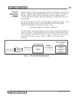
One SmartMUX board is attached to the JARC board using screws and a
pluggable 17-pin header. Two 6-position DIP switches on the SmartMUX
board, labeled SW1 and SW2, set the rack address and the baud rate for the
communications. Refer to Figure 2.
Figure 2. SmartMUX Board
J1
EPROM
I/O Rack Connector
J2
PWR LED (Red – for Power)
LED (Green – for Communications)
Connector
to
JARC J5 or JARC J6
SW1 SW2
1
10
RST
ALE
CLR
SHD
BLUE
GND
CCL
CGD
+5V
Connections to
A-B 1771 I/O
Network


