


INTRODUCTION
1
INTRODUCTION
2/17/95
INTRODUCTION
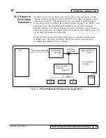
HARDWARE
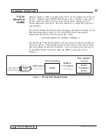
The Allen-Bradley Programmable Logic Controller (PLC) Remote I/O
Gateway allows any drive on the MicroTrac
®
LAN to communicate with an
Allen-Bradley PLC-5 or PLC-3 through the 1771 I/O Network. Both logic
and numeric information can be transferred.
CAUTION
The gateway must be properly grounded. Use star washers that
will cut into the metal of the gateway box when mounting to
ensure proper earth ground.
The Allen-Bradley PLC gateway is a self-contained unit with one JARC
interface board, one SmartMUX interface board, one eight-point local I/O
interface board, and a power supply. The NEMA 1 enclosure contains the
electronics with internal connections for AC power, digital I/O points, and
external connections for the MicroTrac LAN. The initial setup is factory
configured, but depending on the application, the following electronic boards
may require setup.
1.
The JARC board is the interface board which provides the LAN
connection and communicates with the SmartMUX board through dual port
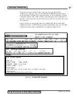
memory contained on the JARC board. A 12-position DIP switch on the
JARC board, labeled SW1, sets the LAN node address (default = 200) and the
rack address (default = 1). Refer to Figure 1.
Figure 1. JARC Interface Board
J5
J6
EPROM
J7
+5 V Ground –5 V PE
J1
• 128K
• 512K
Jumper
J9
XMIT LED D3 (Red)
RECON LED D4 (Yellow)
J3
PCDU
Connection
Fuse
PGM
LED
SW1
1
12
PWR
LED
F1
LAN
Connection
J8
CTS • • • GRD
Jumper
•


