


GENERAL OPERATION
18
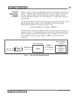
PLC Block Transfer
12/22/94- RD 3196-10
gateway. The fourth rung moves the latest data from the drive into a buffer for
the transition detector of rung 2. The fifth rung executes the read from the
PLC gateway. All 64 words can be handled with block transfers in the PLC
Ladder, if the words are consecutive.
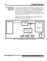
Normally, numeric transfers (inputs and outputs) will use one 16 bit word in a
PLC data file. This word should be in 2’s complement binary format (signed
integer). If the physical input to the PLC is from Binary Coded Decimal
(BCD) thumbwheel switches, then the PLC ladder logic diagram must convert
the BCD number to 2’s complement format before putting it in the appropriate
word of the Block Transfer data file.
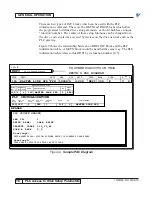
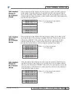
The thumbwheel switch assembly may have a decimal point (i.e. two digits
may exist to the right of the decimal point, allowing numeric inputs to 0.01
precision). Since the 2’s complement number put into the Block Transfer file
will be an integer, not an integer plus fraction, there must be some way of
knowing where the decimal point is located. This is accomplished in the PAC
blocks with the decimal point (DP) parameter. As shown in Figure 10, the DP
for the pertinent NUMI block must be specified as 2.
In some cases, a 16 bit signed integer (+/– 32,768) may not be sufficient for
the required range. For increased range, the IEEE floating point conversion in
the PLC should be used, and the results stored in two consecutive 16 bit words
in the Block Transfer data file. In order for the PLC gateway to expect this
number format, the DP of the appropriate PAC blocks should be specified as
255 (0FFH). Again, note that two consecutive words are used for format, and
only 32 values (0 to 32) can be specified as sub-channels.
To avoid confusion, a single Block Transfer cannot mix integer and IEEE
floating point formats. If the application must use both formats, two Block
Transfer operations are needed, one for the integer numeric and one for the
floating point numeric.
This would then require two gateway racks, since a maximum of one (1) Block
Transfer Write and one (1) Block Transfer Read can be accommodated in each
gateway rack. As with LOGI, multiple drives can be specified to have NUMI
blocks obtaining data from the same data block in a given Block Transfer
Write.
NOTE: In organizing the 64 words of the BTW, group all PLC
initialization values separate from logical inputs for optimal
communication.


