


GENERAL OPERATION
11
MicroTrac to PLC
12/22/94- RD 3196-10
MicroTrac to
PLC (LOGO)
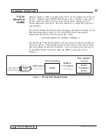
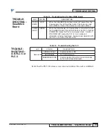
Logic outputs from a PAC schematic to a PLC can be visualized as shown in
Figure 4. Logic output (LOGO) PAC blocks send a logic value from the drive
to the remote device specified by the node, channel, and sub channel defined
for that block. The node number for a single PLC gateway is typically 200.
These logics utilize groups 1-7 for a maximum total of 112 (7 x 16) MicroTrac
to PLC logic bits.
The LAN channel number is in octal notation and corresponds directly with
the A-B PLC rack and group number for the associated simulated A-B input.
In addition, the number will have a 100's prefix digit of 1 that can be
associated with the A-B PLC input "I" notation. Thus:
LAN CHANNEL 124 = INPUT RACK 2, GROUP 4 or I:24
LAN CHANNEL 127 = INPUT RACK 2, GROUP 7 or I:27
The sub channel number will also be in octal, and will directly correspond to
the bit number of the simulated output. Thus, the 16 possible bits are:
LAN SUB CHANNEL 00 = BIT 00
: :
:
LAN SUB CHANNEL 07 = BIT 07
LAN SUB CHANNEL 10 = BIT 10
: :
:
LAN SUB CHANNEL 17 = BIT 17
Each PLC logic input bit can be addressed by no more than one drive. If more
than one drive attempts to initialize the same bit (sub channel) in a given
group, a “Logic Output Allocation Error” message will be sent to the drive
over the LAN.
NOTE: LAN traffic throughput may significantly improved if all logic
values for a particular drive are grouped together and not needlessly
divided between multiple PLC groups.
Figure 4. PAC Logic Output to PLC
TYPICAL LOGO
103-D
LOGO
Node Chan. Sub
200 136 3
LAN Cable
Logic Bits
PLC Gateway
Remote
I/O Cable
PLC Ladder
Logic
I:36/03


