

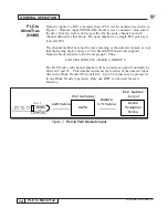
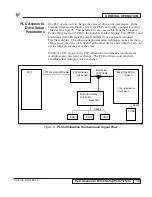


PCDU TERMINAL OPERATION
26
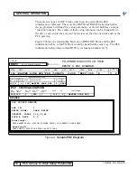
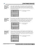
Information Block 3 – Digital Write
12/22/94- RD 3196-10
This block displays the digital (logic) data written by the PLC to the
remote I/O rack simulated by this gateway. This is shown by the
abbreviation “Dig. Wr” followed by the rack and group number, a dash,
and the sixteen-bit digital value displayed in hexadecimal representation.
Dig.Wr X0-????
Where: X is the simulated rack number
Dig.Wr X1-????
???? is the data
Dig.Wr X2-????
Dig.Wr X3-????
Dig.Wr X4-????
Dig.Wr X5-????
Dig.Wr X6-????
Dig.Wr X7-????
This block displays the digital (logic) data written by the PLC to the gateway’s
second rack if it was enabled. This is shown by the abbreviation “Dig.Wr”
followed by the rack and group number, a dash, and the sixteen-bit digital
value displayed in hexadecimal representation.
Dig.Wr Y0-????
Where: Y is the unused rack number
Dig.Wr Y1-????
???? is the data
Dig.Wr Y2-????
Dig.Wr Y3-????
Dig.Wr Y4-????
Dig.Wr Y5-????
Dig.Wr Y6-????
Dig.Wr Y7-????
This information block displays the data elements read by the PLC in the last
block transfer from the gateway’s simulated I/O rack. This is shown by the
abbreviation “Blk.Rd” followed by the rack number, a dash, the element
number within the block, a dash, and the sixteen-bit value displayed in
hexadecimal representation. A block transfer contains 64 elements.
Blk.Rd X-00-????
Where: X is the rack number
Blk.Rd X-01-????
???? is the data
Blk.Rd X-02-????
....
Blk.Rd X-62-????
Blk.Rd X-63-????
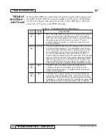
Information
Block 4 –
Digital Write
Information
Block 5 –
PLC Block
Read
Information
Block 3 –
Digital Write


