


Appendix
15.3.1 Load Drive Capacity
1
5
-12
J
Machine-tool Main Axis Drive
The motive force required for the main axis drive, such as a lathe or machining center, is determined using
the cutting motive force. The cutting process requires fixed output characteristics, and the fixed output
control range requires a ratio of 1: 10 to 30. The methods of calculating the required motive force shown
are examples of lathe cutting processing, machining center milling processing, and drill processing. (To
accurately calculate the required force, the condition of the cutting oil, the material of the cutting tools,
the shape, and the hardness of the material being cut all affect the cutting resistance, so these must also
be considered.)
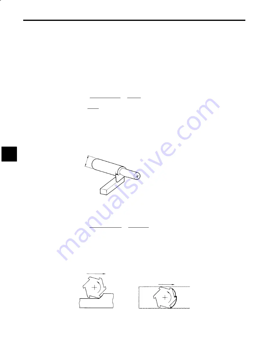
As shown in Fig. 15.14, when using a lathe cutting processing, the object to be cut is rotated, and the blade
is pressed against it to perform the cutting operation, so the motive force
PLC
required to cut can be ex-
pressed using the following equation.
P
C
=
K
S
dLV
60
×
1000
×
η
C
=
dLV
S
C
⋅
η
C
(kW)
V
=
π
DNs
1000
(m/min)
K
S
:
Cutting resistance (N/mm2)
d
:
Cutting depth (mm)
L
:
Length of blade actually performing cutting (i.e., amount of feed per rotation) (mm)
D
:
Diameter of object being processed (mm)
N
S
:
Main axis speed (min
−
1
)
η
C
:
Machine efficiency 0.7 to 0.85
S
C
:
Cutting efficiency (i.e., cutting amount per 1 kW per minute) (CC/kW/min.)
D
d
L
Fig 1
5
.
14
Example of Lathe Cutting Process
As shown in Fig. 15.15, if using milling processing, the blade is mounted to the main axis and rotated to
cut the object being processed, so the motive force
P
F
required can be expressed using the following for-
mula.
P
F
=
K
S
δ
Wf
60
×
1000
2
×
η
F
=
δ
Wf
1000
2
S
F
η
F
(kW)
K
S
:
Cutting resistance (N/mm2)
δ
:
Cutting depth (mm)
W
:
Cutting width (mm)
f
:
Feed speed (mm/min.)
S
F
:
Cutting efficiency (i.e., cutting amount per 1 kW per minute) (CC/kW/min.)
η
F
:
Machine efficiency 0.7 to 0.85
f
f
(a) Side Milling
(b) Front Milling
Fig 1
5
.
15
Example of Milling Processing
15


