4. ENGINE
4-3-2
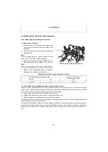
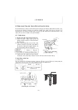
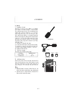
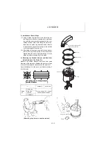
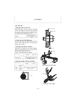
(2) Width and angle of the valve seat
Remove carbon deposits from the seat surface. Mea-
sure the seat width and angle using vernier calipers and
an angle gauge respectively.
[Valve seat correction procedure]
(1) If the seat surface is worn or roughened slightly, lap
the seat surface to a smooth state with a valve com-
pound mixed with oil.
(2) If the seat surface is worn or roughened exces-
sively, correct the seat surface using a seat grinder
or a seat cutter, and finish it according to the above
step (1).
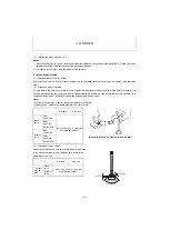
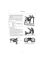
[Procedure for using seat grinder and seat cutter]
(1) Correct the roughened seat surface with a seat
grinder or a seat cutter.
(2) When the seat width is enlarged from the initial
value, correct it by grinding the seat surface with a
70 degrees seat grinder or a seat cutter. Then, grind
the seat surface with a 15 degrees grinder so that
the seat width should be the standard value.
Note :
When using a seat cutter, apply pressure evenly taking
care not to cut the seat surface unevenly.
(3) Knead a valve compound with oil and finish the valve seat by lapping with the compound.
Note :
If any valve requires correction, be sure to measure the oil clearance between the valve stem outside dia. and the
valve guide inside dia. If the oil clearance exceeds the wear limit, replace the valve or the valve guide before correct-
ing the valve seat surface. (For the oil clearance between the valve and the valve guide, refer to the subsection 3 in
this section.)
Standard
Wear limit
Valve
seat
width
Intake
Refer to Section "3-2 1) Nominal and
Allowable Values".
Exhaust
Valve
seat
angle
Intake
Exhaust
Seat grindstone
Angle
(degrees)
Intake valve
30
Exhaust valve
45
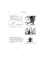
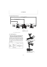
(Measuring the valve seat width)
Seat grinder
Grindstone
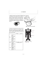
(Valve seat correction angle)
Valve seat
Seat width
70
q
ǰ
15
q
Содержание ViO12-2A
Страница 1: ...SERVICE MANUAL EXCAVATOR ViO12 2A...
Страница 2: ......
Страница 3: ......
Страница 9: ......
Страница 21: ......
Страница 23: ......
Страница 37: ......
Страница 55: ......
Страница 57: ......
Страница 99: ......
Страница 109: ...5 3 1 5 ELECTRIC SYSTEM 5 3 Wiring Diagram...
Страница 114: ......
Страница 117: ...6 HYDRAULIC SYSTEM 6 1 3...
Страница 118: ...6 HYDRAULIC SYSTEM 6 1 4...
Страница 119: ...6 HYDRAULIC SYSTEM 6 1 5 This Page Intentionally Left Blank...
Страница 121: ...6 HYDRAULIC SYSTEM 6 1 7...
Страница 122: ...6 HYDRAULIC SYSTEM 6 1 8...
Страница 123: ...6 HYDRAULIC SYSTEM 6 2 1 6 2 Hydraulic Circuit Schematic...
Страница 125: ...6 HYDRAULIC SYSTEM 6 3 2...
Страница 126: ...6 HYDRAULIC SYSTEM 6 3 3...
Страница 127: ...6 HYDRAULIC SYSTEM 6 3 4 This Page Intentionally Left Blank...
Страница 129: ...6 HYDRAULIC SYSTEM 6 3 6...
Страница 130: ...6 HYDRAULIC SYSTEM 6 3 7...
Страница 131: ...6 HYDRAULIC SYSTEM 6 3 8 This Page Intentionally Left Blank...
Страница 133: ...6 HYDRAULIC SYSTEM 6 3 10...
Страница 134: ...6 HYDRAULIC SYSTEM 6 3 11...
Страница 135: ...6 HYDRAULIC SYSTEM 6 3 12 This Page Intentionally Left Blank...
Страница 137: ...6 HYDRAULIC SYSTEM 6 3 14...
Страница 138: ...6 HYDRAULIC SYSTEM 6 3 15...
Страница 139: ...6 HYDRAULIC SYSTEM 6 3 16 This Page Intentionally Left Blank...
Страница 141: ...6 HYDRAULIC SYSTEM 6 3 18...
Страница 143: ...6 HYDRAULIC SYSTEM 6 3 20 This Page Intentionally Left Blank...
Страница 145: ...6 HYDRAULIC SYSTEM 6 3 22...
Страница 147: ...6 HYDRAULIC SYSTEM 6 3 24 This Page Intentionally Left Blank...
Страница 149: ...6 HYDRAULIC SYSTEM 6 3 26...
Страница 150: ...6 HYDRAULIC SYSTEM 6 3 27...
Страница 151: ...6 HYDRAULIC SYSTEM 6 3 28 This Page Intentionally Left Blank...
Страница 153: ...6 HYDRAULIC SYSTEM 6 3 30...
Страница 155: ...6 HYDRAULIC SYSTEM 6 3 32 This Page Intentionally Left Blank...
Страница 157: ...6 HYDRAULIC SYSTEM 6 3 34...
Страница 159: ...6 HYDRAULIC SYSTEM 6 3 36 This Page Intentionally Left Blank...
Страница 161: ...6 HYDRAULIC SYSTEM 6 3 38...
Страница 162: ...6 HYDRAULIC SYSTEM 6 3 39...
Страница 163: ...6 HYDRAULIC SYSTEM 6 3 40 This Page Intentionally Left Blank...
Страница 165: ...6 HYDRAULIC SYSTEM 6 3 42...
Страница 166: ...6 HYDRAULIC SYSTEM 6 3 43...
Страница 168: ...6 HYDRAULIC SYSTEM 6 3 45...
Страница 169: ...6 HYDRAULIC SYSTEM 6 3 46...
Страница 180: ...6 HYDRAULIC SYSTEM 6 5 7 4 Special tools Unit mm Oil seal installation jig 063145 00EN00 115 10 19 8 31 7...
Страница 219: ...6 HYDRAULIC SYSTEM 6 7 8 1 4 3 8 7 12 10 10 15 a b c Loctite 262 0 30Nm 0 45Nm...
Страница 345: ...7 ADJUSTMENT AND REPAIR 7 5 28 3 Upperstructure Control valve Swivel joint Control valve Boom swing cylinder...
Страница 348: ...7 ADJUSTMENT AND REPAIR 7 5 31 6 Control Levers Pilot valves Control valve...
Страница 349: ...7 ADJUSTMENT AND REPAIR 7 5 32 7 Upperstructure Implement Bucket cylinder Arm cylinder...
Страница 351: ...7 ADJUSTMENT AND REPAIR 7 5 34 9 Undercarriage High speed travel solenoid valve...
Страница 359: ......
Страница 360: ...CHAPTER 8 PERIODIC INSPECTION AND SERVICING 8 1 List of Periodic Inspection and Servicing 8 1...
Страница 361: ......
Страница 364: ...CHAPTER 9 FUEL LUBE OIL AND GREASE RECOMMENDED 9 Fuel Lube Oil and Grease Recommended 9 1...
Страница 365: ......
Страница 367: ......
Страница 369: ......
Страница 406: ...CHAPTER 11 REFERENCE DATA 11 1 Specifications for Attachment 11 1...
Страница 407: ......


