


6.
HYDRAULIC SYSTEM
6-
6
-10
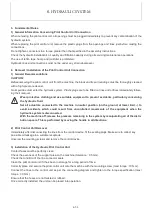
6. Disassembly and Reassembly
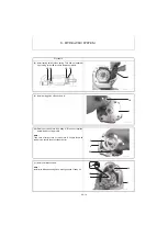
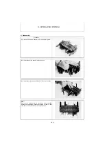
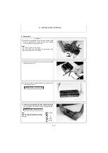
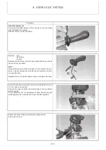
1) Precautions for Disassembly and Reassembly
• Precautions for disassembly
(1) Since the parts of the hydraulic equipment are precision-made for tight clearances, be sure to perform disassem-
bly and reassembly in a clean area that is free from dust.
(2) Prepare clean tools and treated oil, and handle the parts carefully.
(3) First clean the external surfaces of the removed assemblies.
(4) Before beginning disassembly, review the drawings of the internal structure and prepare the required parts
according to the purpose and extent of the disassembly.
In principle, replace the removed seals and rings with new ones. As some replacement parts are available only
as a subassembly, refer to the parts catalog to prepare the necessary subassemblies in advance.
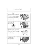
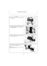
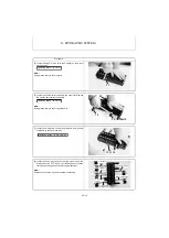
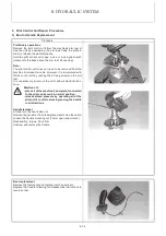
• Precautions for reassembly
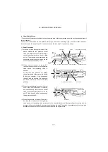
(1) Handling of O-rings
[1] Lubricate the O-rings and the O-ring fitting seats with clean grease or hydraulic oil.
[2] Do not damage the O-rings in handing or distort them by heat.
[3] Do not stretch the O-rings so strongly as to deform them permanently.
[4] Avoid rolling the O-rings when fitting them.
A distorted O-ring may not return to its original shape, and therefore, may cause oil leak.
(2) Before beginning reassembly, check that the mating surfaces of each section have no treated oil or hydraulic oil
on the outer surface of the O-ring grooves in them. If reassembly is performed without such oil, it may be mis-
taken for oil leak.
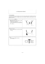
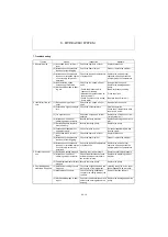
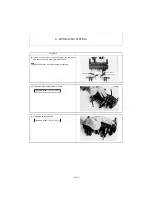
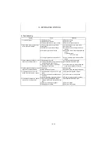
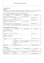
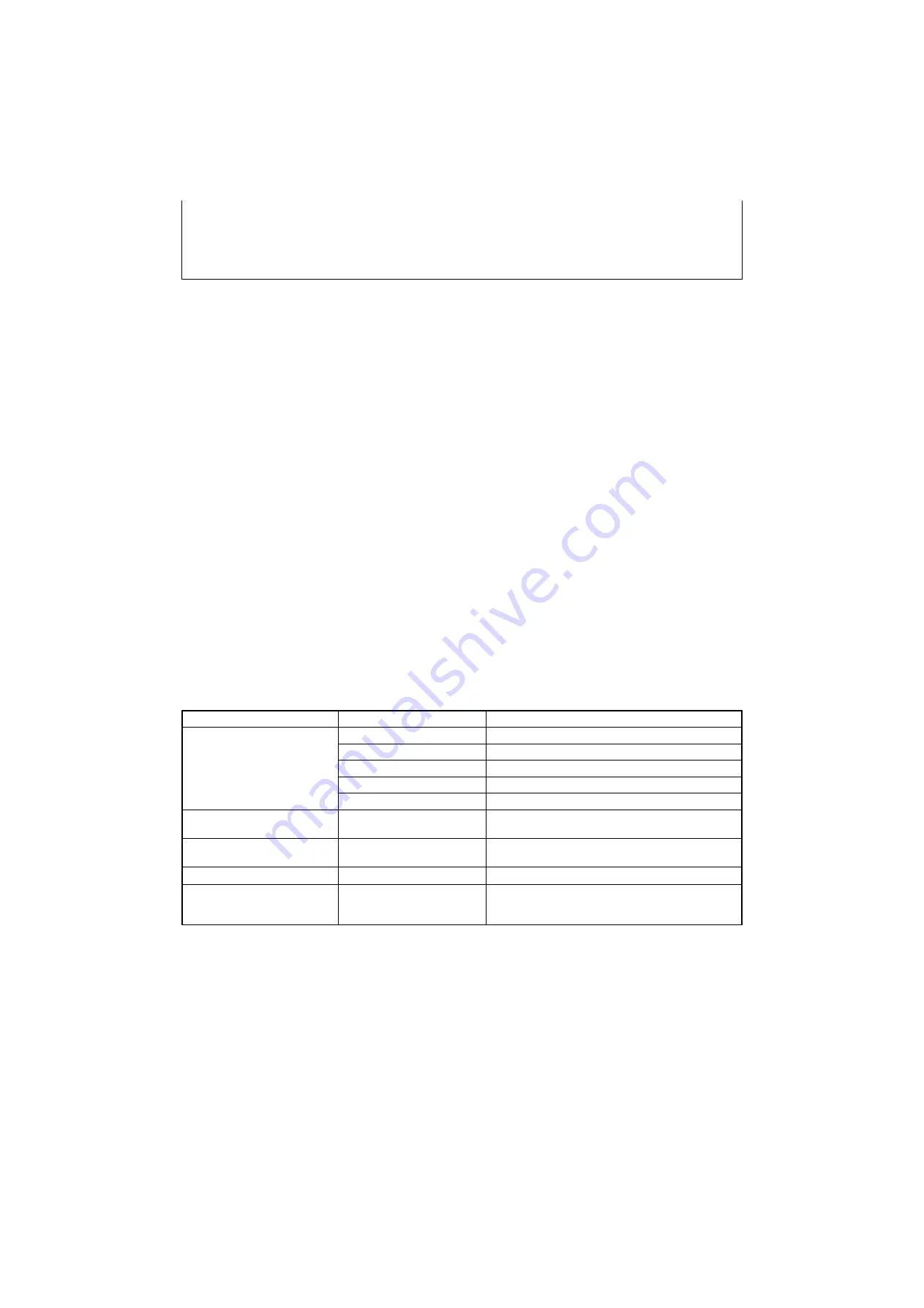
2) Tools for Disassembly and Reassembly
Tool
Nominal size
Remarks
Hexagon socket screw key
(Hexagon wrench)
(
mm
)
3
For hexagon socket set screw M6
4
For hexagon socket head bolt M5
5
For hexagon socket head plug R (PT) 1 / 8
6
For hexagon socket head plug G (PF) 1 / 4
8
For hexagon socket head plug G (PF) 3 / 8
Wrench or box wrench
(mm)
8, 10, 13, 21 and 22
Screwdriver for cross recessed
head screws
For cross recessed pan-head screw M5
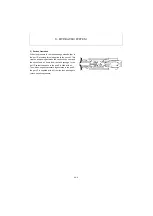
Rod (mm)
Ø
45 to 100
For disassembly and reassembly of spring center
Torque wrench (N·m)
1
9.6 to 98.1
Smaller than 19.6
For system relief valve, circuit relief valve, and anti-cavita-
tion valve
For nut M8, spring case and pilot case
Содержание ViO12-2A
Страница 1: ...SERVICE MANUAL EXCAVATOR ViO12 2A...
Страница 2: ......
Страница 3: ......
Страница 9: ......
Страница 21: ......
Страница 23: ......
Страница 37: ......
Страница 55: ......
Страница 57: ......
Страница 99: ......
Страница 109: ...5 3 1 5 ELECTRIC SYSTEM 5 3 Wiring Diagram...
Страница 114: ......
Страница 117: ...6 HYDRAULIC SYSTEM 6 1 3...
Страница 118: ...6 HYDRAULIC SYSTEM 6 1 4...
Страница 119: ...6 HYDRAULIC SYSTEM 6 1 5 This Page Intentionally Left Blank...
Страница 121: ...6 HYDRAULIC SYSTEM 6 1 7...
Страница 122: ...6 HYDRAULIC SYSTEM 6 1 8...
Страница 123: ...6 HYDRAULIC SYSTEM 6 2 1 6 2 Hydraulic Circuit Schematic...
Страница 125: ...6 HYDRAULIC SYSTEM 6 3 2...
Страница 126: ...6 HYDRAULIC SYSTEM 6 3 3...
Страница 127: ...6 HYDRAULIC SYSTEM 6 3 4 This Page Intentionally Left Blank...
Страница 129: ...6 HYDRAULIC SYSTEM 6 3 6...
Страница 130: ...6 HYDRAULIC SYSTEM 6 3 7...
Страница 131: ...6 HYDRAULIC SYSTEM 6 3 8 This Page Intentionally Left Blank...
Страница 133: ...6 HYDRAULIC SYSTEM 6 3 10...
Страница 134: ...6 HYDRAULIC SYSTEM 6 3 11...
Страница 135: ...6 HYDRAULIC SYSTEM 6 3 12 This Page Intentionally Left Blank...
Страница 137: ...6 HYDRAULIC SYSTEM 6 3 14...
Страница 138: ...6 HYDRAULIC SYSTEM 6 3 15...
Страница 139: ...6 HYDRAULIC SYSTEM 6 3 16 This Page Intentionally Left Blank...
Страница 141: ...6 HYDRAULIC SYSTEM 6 3 18...
Страница 143: ...6 HYDRAULIC SYSTEM 6 3 20 This Page Intentionally Left Blank...
Страница 145: ...6 HYDRAULIC SYSTEM 6 3 22...
Страница 147: ...6 HYDRAULIC SYSTEM 6 3 24 This Page Intentionally Left Blank...
Страница 149: ...6 HYDRAULIC SYSTEM 6 3 26...
Страница 150: ...6 HYDRAULIC SYSTEM 6 3 27...
Страница 151: ...6 HYDRAULIC SYSTEM 6 3 28 This Page Intentionally Left Blank...
Страница 153: ...6 HYDRAULIC SYSTEM 6 3 30...
Страница 155: ...6 HYDRAULIC SYSTEM 6 3 32 This Page Intentionally Left Blank...
Страница 157: ...6 HYDRAULIC SYSTEM 6 3 34...
Страница 159: ...6 HYDRAULIC SYSTEM 6 3 36 This Page Intentionally Left Blank...
Страница 161: ...6 HYDRAULIC SYSTEM 6 3 38...
Страница 162: ...6 HYDRAULIC SYSTEM 6 3 39...
Страница 163: ...6 HYDRAULIC SYSTEM 6 3 40 This Page Intentionally Left Blank...
Страница 165: ...6 HYDRAULIC SYSTEM 6 3 42...
Страница 166: ...6 HYDRAULIC SYSTEM 6 3 43...
Страница 168: ...6 HYDRAULIC SYSTEM 6 3 45...
Страница 169: ...6 HYDRAULIC SYSTEM 6 3 46...
Страница 180: ...6 HYDRAULIC SYSTEM 6 5 7 4 Special tools Unit mm Oil seal installation jig 063145 00EN00 115 10 19 8 31 7...
Страница 219: ...6 HYDRAULIC SYSTEM 6 7 8 1 4 3 8 7 12 10 10 15 a b c Loctite 262 0 30Nm 0 45Nm...
Страница 345: ...7 ADJUSTMENT AND REPAIR 7 5 28 3 Upperstructure Control valve Swivel joint Control valve Boom swing cylinder...
Страница 348: ...7 ADJUSTMENT AND REPAIR 7 5 31 6 Control Levers Pilot valves Control valve...
Страница 349: ...7 ADJUSTMENT AND REPAIR 7 5 32 7 Upperstructure Implement Bucket cylinder Arm cylinder...
Страница 351: ...7 ADJUSTMENT AND REPAIR 7 5 34 9 Undercarriage High speed travel solenoid valve...
Страница 359: ......
Страница 360: ...CHAPTER 8 PERIODIC INSPECTION AND SERVICING 8 1 List of Periodic Inspection and Servicing 8 1...
Страница 361: ......
Страница 364: ...CHAPTER 9 FUEL LUBE OIL AND GREASE RECOMMENDED 9 Fuel Lube Oil and Grease Recommended 9 1...
Страница 365: ......
Страница 367: ......
Страница 369: ......
Страница 406: ...CHAPTER 11 REFERENCE DATA 11 1 Specifications for Attachment 11 1...
Страница 407: ......


